Short answer: Wind engineering for a kinetic facade spans two extremes: louvers must begin rotating below 0.9 m/s (about 2 mph), yet the assembly must carry a 45 m/s service wind verified by finite-element analysis. INDECO blades in 6063-T5 aluminium ride stainless pivots with return springs, validated against 150+ wind load cases for 99.8% reliability.
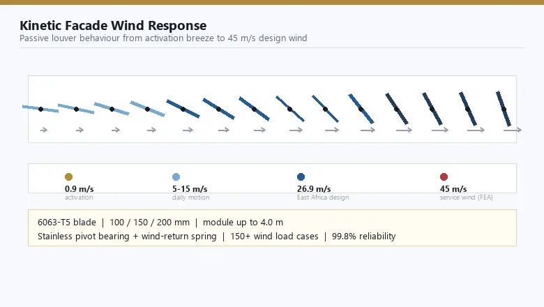
A kinetic facade lives on moving air, so wind is simultaneously its power source and its worst enemy. Designing one means solving both at once: the same louver that must flutter in a breeze you can barely feel must also hold together in a 45 m/s design storm. This guide walks through the full wind brief for a kinetic louver elevation — activation thresholds, design wind speed, pressure zones, blade loads, fatigue and verification.
What is kinetic facade wind engineering?
It is the discipline of sizing a moving facade skin across three wind states: activation (the breeze that starts the motion), service (the strongest wind the facade regularly sees) and survival (the code design event). Because dynamic pressure grows with the square of speed (q = 0.613 V² in SI units), the spread between these states is enormous — roughly a factor of 2,500 in pressure between a 0.9 m/s activation breeze and a 45 m/s service wind. New to the product first? Start with the kinetic facade primer.
| Wind state | Speed | Dynamic pressure q = 0.613 V² | What the facade does |
|---|---|---|---|
| Activation breeze | 0.9 m/s (≈2 mph) | ≈0.5 Pa | Blades begin free rotation; shading starts with zero power |
| Daily site winds | 5–15 m/s | 15–138 Pa | Continuous passive motion; rhythm of light and shadow; airflow through the screen |
| Gusts and storm fronts | 20–30 m/s | 245–552 Pa | Blades ride out gusts; brackets and pivots stressed toward FEA limits |
| Design service wind | 45 m/s | ≈1,241 Pa | Full 150+ load-case verification; 99.8% system reliability |
How do wind-responsive louvers start moving?
There is no motor and no sensor. Each aerofoil blade balances on a stainless pivot bearing with a wind-return spring. The spring preloads the pivot with a tiny resisting torque; the moment wind pressure on the blade area exceeds that torque, the blade rotates freely. The threshold on an INDECO system is below 0.9 m/s — less wind than it takes to lift a sheet of paper. When the air calms, the spring returns the blade to its resting angle, so the elevation resets itself thousands of times a day without any control system.
Blade width tunes this behaviour: at 100, 150 or 200 mm width and module heights up to 4.0 m, a wider blade starts earlier in lighter air but also catches more storm load — one reason the wind brief must be solved for both ends of the scale, not just the design event.
What design wind speed should a kinetic facade carry?
The number comes from the governing code, not from habit: a 50-year return basic wind speed adjusted for terrain, height and building importance — EN 1991-1-4 in Europe, ASCE 7 in the Americas, and the Saudi Building Code (SBC) with Mostadam sustainability requirements on our Gulf projects, where the design ambient is 45 °C. Two INDECO reference points: the East Africa CBD Tower was engineered for a design wind of about 26.9 m/s, while the Gulf Cultural Landmark Pavilion on an exposed coastal site was verified to 45 m/s by finite-element analysis.
Why do corners and edges govern the louver design?
Wind pressure is not uniform over an elevation. Flow separation at building corners and the parapet creates suction peaks that standards codify as local pressure zones: corners typically see 1.7–2.0× the field pressure, and edge or parapet strips about 1.3–1.6×. That is why corner modules get denser blades or closer bracket spacing, and why pivot hardware is selected against the corner case, not the average one.
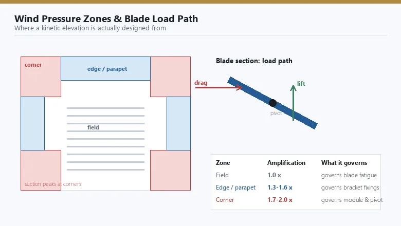
| Facade zone | Pressure amplification | Design consequence |
|---|---|---|
| Field (mid-elevation) | 1.0× | Governs blade fatigue and everyday motion |
| Edge / parapet strips | ≈1.3–1.6× | Governs bracket and sub-frame fixings |
| Corners | ≈1.7–2.0× | Governs pivot selection and module spacing — the zone that fails first if ignored |
How much load does one blade actually take?
A worked example makes the order of magnitude concrete. A 200 mm blade on a 4.0 m module presents about 0.8 m² of projected area. At the 45 m/s service wind, q ≈ 1,241 Pa, so with a net pressure coefficient around 1.2 the blade carries roughly 1.2 kN — the weight of a large adult, hanging off a pivot the size of a coin, several thousand times a year. Finite-element analysis checks the blade section, the pivot, the arm and the module anchorage as one load path, not as isolated parts.
How many movement cycles must a pivot survive?
This is the question that separates a kinetic facade from a static one. A breezy coastal site logs activation-level winds on hundreds of days a year; with blades oscillating at 1–3 Hz during motion, a single elevation can accumulate on the order of a million movements per year, or more than 10 million cycles over the 25+ year design life. The sealed stainless bearing and wind-return spring are therefore fatigue-checked, run dry without lubrication, and backed by the 99.8% system reliability figure. Inspection intervals for that duty are set out in the kinetic facade maintenance guide.
How is wind performance verified before delivery?
Verification is documentary, not rhetorical. Every elevation is checked by finite-element analysis across 150+ load cases — pressure magnitudes, wind angles, positive and negative — combined with code wind profiles for the site. Anchorage is proof-tested to 1.5× design load with A2/A4 stainless fixings and isolation washers, and the adjacent sealed envelope is pressure-tested to standard curtain wall performance levels (our Gulf Waterfront Commercial Tower glazing case carries a 4.5 kPa structural rating).
| Check | Method | Acceptance |
|---|---|---|
| Blade & pivot strength | FEA across 150+ pressure and angle combinations | Stresses within 6063-T5 allowables at 45 m/s |
| Module anchorage | Proof loading to 1.5× design load on sub-frame fixings | A2/A4 stainless, isolation washers, no permanent set |
| Site wind profile | Code basic wind speed + terrain, height, importance (EN 1991-1-4 / ASCE 7 / SBC) | 50-year return event covered with margin |
| Motion & return | Function test at activation threshold | Free rotation below 0.9 m/s; full spring return to rest |
Which climates change the wind brief?
A Gulf coastal site stacks every aggressor at once: 45 °C design ambient, C4–C5 salt exposure on the ISO 9223 scale, and abrasive dust. Blades respond with marine-grade 6063-T5 alloy and a finish that survives the same wind it shades against — anodising to AA25 (oxide 200–500 HV, salt-spray tested 500–4,000 h, A2 fire classification, applied by our anodizing partner in Guangdong) or 2-coat PVDF at 25 µm. Perforated screen blades are the wind engineer's second lever: opening the blade area cuts net pressure where cyclone or typhoon zones push design speeds up. The full climate logic is in the Gulf climate design guide.
Wind is the whole story of this product class: the input, the power supply and the design case. Get the wind brief right — activation, service, zones, fatigue — and the facade runs on it for decades.
Key takeaways
- A kinetic facade is engineered across two wind extremes: motion below 0.9 m/s activation and survival at up to 45 m/s service wind, verified by FEA over 150+ load cases.
- Dynamic pressure scales with speed squared (q = 0.613 V²): 45 m/s exerts about 1,241 Pa — roughly 2,500× the activation breeze.
- Corner zones see 1.7–2.0× field suction and govern pivot, bracket and module design; edge strips run 1.3–1.6×.
- The single moving assembly — stainless pivot bearing plus wind-return spring — is fatigue-checked beyond 10 million cycles over a 25+ year life.
- Verification follows the governing code (EN 1991-1-4, ASCE 7, Saudi SBC + Mostadam) with 99.8% system reliability.
Frequently asked questions
What wind speed activates a kinetic facade?
INDECO louvers start moving below 0.9 m/s — about 2 mph, a breeze you can barely feel. Each aerofoil blade balances on a stainless pivot bearing with a wind-return spring, so wind pressure turns it freely and the spring brings it back to rest when the air calms.
How is kinetic facade wind load calculated?
Engineers start from the code basic wind speed — EN 1991-1-4, ASCE 7 or the Saudi SBC — apply terrain, height and importance factors, and convert to pressure with q = 0.613 V². Corner and edge zones amplify pressure, and FEA checks the blades across 150+ load combinations up to 45 m/s.
What happens to kinetic louvers in a storm?
Nothing breaks and nothing needs switching off. The passive blades simply angle with the gusts, shedding load as they rotate, while pivots and brackets are FEA-verified for service winds up to 45 m/s — the level matched on our Gulf Cultural Landmark Pavilion design case.
How long do the moving parts last?
The only moving assembly is a sealed stainless bearing with a return spring, designed to run dry. A breezy coastal site can log over a million blade movements a year, so pivots are fatigue-checked for more than 10 million cycles across the 25+ year design life.
Do kinetic facades work in typhoon and cyclone zones?
Yes, with the right brief. Perforated screen blades reduce net wind pressure, corner modules are densified where suction peaks, and the elevation is verified to the site's 50-year return wind. Our East Africa CBD Tower case was engineered for 26.9 m/s; Gulf coastal cases reach 45 m/s.
Specifying a kinetic facade for a high-wind site?
Send us the site wind speed, terrain category and elevation geometry. We return a wind-load dossier — activation threshold, FEA verification across 150+ cases, pressure-zone mapping and finish specification — matched to your governing code. See the Kinetic Louver Facade range, browse the facade FAQ, or talk to our engineering team.