
Every moving facade has to answer one question before anything else: what makes the blades move? On a wind-responsive kinetic facade the answer is the wind itself — a passive mechanism with no motor, no sensor, no cable and no power. On a motorised dynamic facade the answer is an actuator commanded by a controller that reads sensors and talks to the building management system. Both animate the elevation, but they differ in every practical dimension: energy, wiring, failure modes, commissioning and whole-life cost. New to the product class? Start with the kinetic facade primer.
What is kinetic facade actuation?
Actuation is the mechanism that converts an input — wind, sunlight or a control signal — into blade movement. Two families cover almost every project. A passive wind-driven louver is balanced on a pivot and driven by air pressure on the blade; a motorised louver is driven by an electric actuator following a control sequence. The choice is not about which one moves more elegantly. It is about whether the facade must follow the sun on a schedule, or simply respond to air moving across it.
| Attribute | Passive wind-driven | Motorised |
|---|---|---|
| Input | Air pressure on the blade | Sensor reading and control signal |
| Moving hardware | One stainless pivot + return spring per blade | Actuator, drive shaft, limit switches, panel, cabling |
| Energy | Zero | ~40–80 W standby plus travel energy |
| Response | Under 1 s, inherent to the mechanism | 15–35 s end-to-end |
| Behaviour in a blackout | Keeps shading | Holds a defined fail position |
How does passive wind actuation work?
It is a torque balance, not a control loop. Each aerofoil blade in marine-grade 6063-T5 aluminium hangs on a stainless steel bearing with a wind-return spring. The spring applies a small resisting torque at the pivot; the moment wind pressure on the blade area exceeds it, the blade rotates freely. INDECO sets that threshold below 0.9 m/s — about 2 mph, less air than it takes to lift a sheet of paper. When the air calms, the spring returns the blade to its rest angle, so the elevation resets itself thousands of times a day with no controller, no sensor and no power supply.
- Activation threshold: below 0.9 m/s (≈ 2 mph)
- Moving parts per blade: one sealed stainless bearing plus wind-return spring, running dry
- Blade options: aerofoil, flat fin or perforated screen in 100 / 150 / 200 mm widths
- Module height: up to 4.0 m per unit
- Service wind: up to 45 m/s, project-verified by FEA across 150+ load cases
- Energy: zero — no motor, sensor, cable or power supply
- Design life: 25+ years with periodic inspection
Because the blade width changes both the driving torque and the storm load, widths and pivot preload are tuned together against the site wind brief — the subject of our kinetic facade wind load guide.
How does a motorised kinetic facade work?
A motorised elevation replaces the spring balance with a drive line. A 24 V DC rotary or linear actuator torques a shaft carrying a group of blades — typically six to fifteen — through 0–90° of travel in 10–30 seconds. Sensors feed a controller, and the controller exposes points to the BMS. Typical field devices are an anemometer, a solar irradiance sensor, a rain contact and sometimes interior illuminance or occupancy sensing, with a wind-stow command usually set at 20–25 m/s.
| Component | Typical specification | Why it matters |
|---|---|---|
| Actuator | 24 V DC, 20–60 N·m per drive line, IP65 minimum, 0–90° in 10–30 s | Sets travel time and the wind-stow threshold that must precede a gust |
| Anemometer | 0.5–50 m/s range, ±0.2 m/s typical accuracy | Single point of truth for wind-stow; must be sited clear of facade turbulence |
| Irradiance sensor | 0–2,000 W/m² | Turns shading into a daylight strategy instead of a guess |
| Control panel | One per zone, shaded and ventilated | Electronics derate above 40–50 °C; a 45 °C design ambient matters here |
| Cabling | Power, bus and feedback per drive line, home-run to riser | Adds cost and a service access obligation on every zone |
| Surge protection | Type 1/2 SPD on exposed elevations | Motors and controllers on a tower are lightning-sensitive |
How much energy does actuation actually cost?
Passive is zero by definition. Motorised is small, but never zero, and the standby load runs all year. Take a reference elevation of 2,000 m² carrying about 1,600 blades on 40 drive lines. Forty actuators drawing 1–2 W each on standby give roughly 40–80 W continuous — about 440 kWh/yr before a single blade moves. Add travel: 1,200 W of simultaneous drive power for 20 s across 2,000 repositioning events a year is a further 13 kWh. The energy total is modest against the chiller load the screen removes, but the capital number is not: actuators, panels, cabling and commissioning typically add 15–30% to the screen package, and actuator replacement at 10–15 years sits inside a 25+ year facade life.
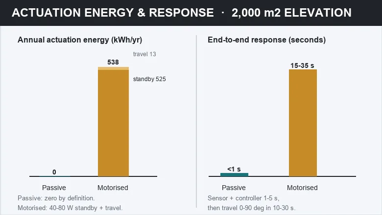
| Item (2,000 m² elevation, 40 drive lines) | Passive wind-driven | Motorised |
|---|---|---|
| Standby draw | 0 W | 40–80 W continuous |
| Annual travel energy | 0 kWh | ≈13 kWh at 2,000 moves/yr |
| Annual actuation energy | 0 kWh | ≈440–600 kWh |
| Controls capex | None | +15–30% of the screen package |
| Interval replacement | Bearing fatigue-checked beyond 10 M cycles | Actuator overhaul or replacement at 10–15 years |
What happens to the facade when the power fails?
This is where the passive mechanism wins outright. With no motor, no controller and no supply, there is nothing to fail: the louvers keep shading through a blackout, a generator changeover or a lightning-induced panel trip, then resume moving the instant the wind picks up again. A motorised elevation must instead define a fail position — normally fail-open so the blades shed wind load, occasionally fail-closed to protect an interior — and hold it with a spring return or a UPS-sized standby supply. In Gulf projects with a 45 °C design ambient there is a second issue: a sealed actuator enclosure in full sun can exceed 70 °C internally, so panels need shading or ventilation, and every one of those provisions is a component that can fail.
How is an elevation divided into control zones?
Zoning is the same exercise whether the drive is wind or wire: group blades that see the same sun and the same wind. Elevations are normally split by orientation first — four zones on a rectangular tower, six to eight where a curved or faceted form creates its own micro-climates — then by height, because wind speed rises with height and the parapet strip behaves differently from mid-elevation. Corner zones, which see 1.7–2.0× the field pressure, are usually separated so their stow or override logic can be tightened independently.
| Zone | Basis | Typical grouping | Design note |
|---|---|---|---|
| South elevation | Highest solar gain | 1–2 drive groups | Carries the shading duty |
| East and West | Low-angle sun | 1 group each, split high/low | Glare events drive repositioning |
| North elevation | Low solar gain | 1 group | Motion is largely aesthetic |
| Corners | 1.7–2.0× field suction | Separate zone | Tighter stow threshold |
| Parapet and top two floors | 1.3–1.6× suction, higher wind speed | Separate zone | First zone to reach stow |
What does BMS integration actually require?
Integration is a point-list exercise, not a protocol debate. Every zone needs read points for blade angle feedback (0–90°), drive alarm, facade wind speed and direction, and irradiance; every zone needs write points for the setpoint or scene, the wind-stow command and a maintenance lockout. The honest part is the latency budget: 1–5 s for sensing and control plus 10–30 s of travel gives a 15–35 s end-to-end reposition — slower than the gust it is reacting to, which is exactly why the stow threshold has to be conservative rather than reactive.
- Read points: blade angle, drive status, zone alarm, wind speed, wind direction, irradiance, panel temperature
- Write points: scene or setpoint, wind-stow command, maintenance lockout, manual override
- Protocols: BACnet/IP, Modbus TCP or KNX, with a hard-wired override as fallback
- Trending: log commanded versus actual angle to catch a lazy actuator before it jams
| Commissioning stage | Test | Acceptance |
|---|---|---|
| Factory | Actuator stroke, torque and limit switch setting | Full 0–90° repeatable, no stall at the limit |
| On site, per drive line | Full stroke under blade load | Angle feedback tracks command within ±2° |
| Per zone | Sequence test for each scene | Every blade in the zone reaches angle within 35 s |
| Wind | Simulated stow trigger at the set threshold | Elevation reaches fail position; alarm logged |
| Handover | Two to four week trend log | No nuisance alarms; seasonal re-commissioning agreed |
How reliable is each approach?
Compare component counts, not adjectives. A passive blade has exactly one moving assembly — a sealed stainless bearing with a return spring, fatigue-checked beyond 10 million cycles and quoted at 99.8% system reliability with FEA verification across 150+ wind load cases. A motorised elevation adds hundreds of outdoor devices: actuators, limit switches, sensors, junction boxes, a control panel. Each has its own failure rate, and system availability is roughly the product of them all. That does not make motorised the wrong choice — it makes the maintenance contract a load-bearing part of the design. Inspection intervals for both paths are set out in the kinetic facade maintenance guide.
Which actuation type fits your project?
Use the decision table below. In our experience most towers, landmarks and remote sites want the passive answer, because the wind is free, reliable and already on site; a motorised or hybrid zone earns its cost only where the brief demands a sun-following or glare-driven response, or where the facade is a retrofit onto an existing control system.
| Criterion | Passive | Motorised | Hybrid |
|---|---|---|---|
| Actuation energy | 0 kWh | ≈440–600 kWh/yr at 2,000 m² | Low, limited to functional zones |
| Response to a gust | Under 1 s, inherent | 15–35 s end-to-end | Passive zones fast, driven zones slow |
| Glare and daylight targeting | Follows wind, not sun | Follows sun and schedule | Best of both, at higher coordination cost |
| Power outage | Keeps working | Needs fail position or UPS | Partly degraded |
| Controls capex | None | +15–30% | Moderate |
| Outdoor field devices | One per blade | Hundreds | Tens to hundreds |
| Best fit | Towers, landmarks, coastal and remote sites, 45 °C Gulf elevations | Atria and auditoria needing targeted glare control | Feature elevation plus functional zones |
Either way, the passive core is the part that has to be right: a mechanism that moves on a breeze and survives a 45 m/s storm cannot be value-engineered after the fact. See the Kinetic Louver Facade range for the blade and pivot options, or read how the same elevation behaves in hot, arid Gulf climates.
Key takeaways
- Passive kinetic louvers need no motor, sensor, cable or power: each blade balances on a stainless pivot with a wind-return spring and starts moving below 0.9 m/s.
- A motorised elevation on 2,000 m² adds 40–80 W of continuous standby draw, roughly 440–600 kWh/yr, and 15–30% to the screen package cost.
- End-to-end response is under 1 s for a passive blade but 15–35 s for a motorised loop, so wind-stow thresholds must be conservative rather than reactive.
- Zoning works the same way for both: orientation first, then height, with corner zones at 1.7–2.0× field pressure controlled separately.
- Reliability tracks component count — 99.8% system reliability with one moving assembly per blade, versus hundreds of outdoor devices on a motorised elevation.
Frequently asked questions
Do kinetic facades need motors?
No. INDECO kinetic louvers need no motor, sensor or power supply: each blade balances on a stainless pivot with a wind-return spring and begins rotating below 0.9 m/s. Motorised systems exist where a project needs solar-following or glare-driven motion rather than wind-driven motion, but they add actuators, panels, cabling and a maintenance obligation to the elevation.
How much electricity does a motorised kinetic facade use?
For a 2,000 m² elevation on about 40 drive lines, expect 40–80 W of continuous standby draw and roughly 440–600 kWh a year including travel energy. The energy itself is small beside the cooling the screen saves, but the controls package typically adds 15–30% to screen cost and actuators need replacement at 10–15 years.
What happens to kinetic louvers during a power cut?
Passive louvers keep working: with no motor and no power supply there is nothing to fail, so the elevation continues shading through a blackout or generator changeover. Motorised louvers must be given an explicit fail position — usually fail-open to shed wind load — held either by a spring return or by a UPS-sized standby supply.
Can a kinetic facade connect to the building BMS?
Yes, when it is motorised. Typical points are blade angle feedback, wind speed and direction, irradiance, zone alarm, setpoint and manual override, exchanged over BACnet/IP, Modbus TCP or KNX. A passive system has no field devices to integrate, though site anemometers are often logged separately so shading performance can be verified later.
Which is more reliable, passive or motorised kinetic facades?
Passive, because the only moving assembly per blade is a sealed stainless bearing and return spring, fatigue-checked beyond 10 million cycles and quoted at 99.8% system reliability. A motorised elevation adds hundreds of outdoor devices — actuators, limit switches, sensors, junction boxes — each with its own failure rate, so availability depends on the whole chain and on the maintenance contract.
Deciding between passive and motorised actuation?
Send us the elevation area, orientation schedule and wind brief. We return an actuation comparison for your facade — blade and pivot selection, energy and component count for a motorised alternative, zoning layout and the finish specification for your climate. See the Kinetic Louver Facade range, browse the facade FAQ, or talk to our engineering team.