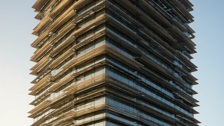
Almost every kinetic facade is sold on shading. The same hardware, however, is the only part of a sealed envelope that can open and close by itself, which makes it the natural actuator for a naturally ventilated floor plate. Get the ventilation design right and the screen earns its cost twice: it cuts solar gain, and it removes the fan energy and the ductwork that would otherwise run to the perimeter.
Get it wrong and the building has an expensive moving screen that is kept shut because the floor overheats, or one that is kept open because the air is stale — and the controls fight each other. This article sets out the ventilation side with the numbers we use in design: free area at each blade angle, discharge coefficients, a full air-change calculation for a 1,200 m² floor plate, the temperature at which natural ventilation stops working, and the dust, noise and smoke details that decide whether the strategy survives commissioning. It follows the daylight and glare article, the rain and drainage article and the passive versus motorised comparison.
What is kinetic facade natural ventilation and how does it work?
Natural ventilation is the supply and exhaust of air driven by pressure differences rather than fans. In a kinetic facade the moving louvre screen becomes the variable opening: the blades rotate, the free area between them changes, and the airflow through the elevation follows. Two forces do the work. Wind creates a pressure difference between the windward and leeward faces, and buoyancy creates a pressure difference between low and high openings when indoor and outdoor air are at different temperatures — the stack effect.
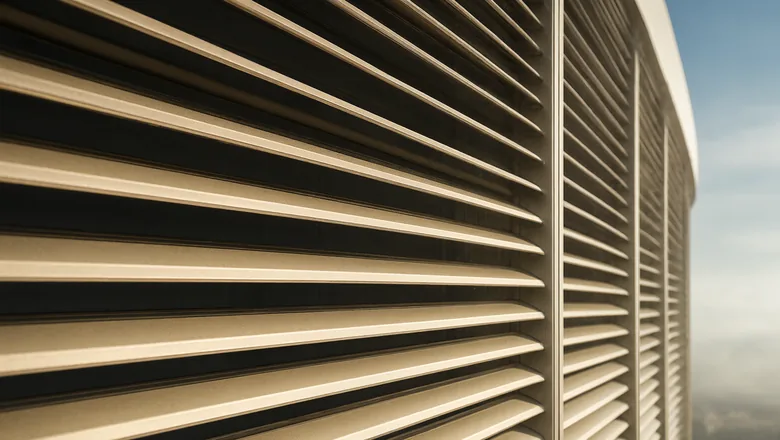
The behaviour that makes a passive screen useful is that it self-regulates in the right direction. INDECO blades begin to move at 0.9 m/s and rotate further as wind speed rises, so free area increases exactly when the driving pressure is available and falls back to 24% when the air is still. A still day therefore gets background ventilation rather than a wide-open hole, and a windy day gets the flow the pressure can support. That is the opposite of a fixed louvre, which is sized for one condition and wrong for the rest of the year.
The pressure available is small, and that is the first thing to internalise. Dynamic pressure follows q = 0.613 V², so 0.9 m/s gives 0.5 Pa and 3 m/s gives only 5.5 Pa — about half a millimetre of water. Across a building with a combined pressure coefficient difference of 0.9, the effective driving pressure at 3 m/s is around 5 Pa, which supports an opening velocity near 2.9 m/s in theory and 1.0–1.5 m/s once internal resistance is included. Every design decision that adds resistance — insect mesh, acoustic baffles, long ducted inlets — takes a large share of a very small budget.
| Wind speed | Dynamic pressure q | Driving pressure at ΔCp 0.9 | Theoretical opening velocity | Practical design velocity |
|---|---|---|---|---|
| 0.9 m/s (blade activation) | 0.5 Pa | 0.45 Pa | 0.87 m/s | Below useful range |
| 1.5 m/s | 1.4 Pa | 1.2 Pa | 1.4 m/s | 0.5–0.8 m/s |
| 3.0 m/s | 5.5 Pa | 5.0 Pa | 2.9 m/s | 1.0–1.5 m/s |
| 5.0 m/s | 15.3 Pa | 13.8 Pa | 4.8 m/s | 1.5–2.0 m/s |
| 45 m/s (design storm) | 1,241 Pa | 1,117 Pa | — | Closed or damped |
Note what the first row means. At the 0.9 m/s activation threshold the wind can push air through an opening at less than 0.9 m/s, which is below the speed at which occupants feel useful air movement. The blade starts to move at the same moment the wind stops being a useful ventilation source — which is why passive ventilation in hot still climates needs a stack, a solar chimney or mechanical assistance, and cannot be sold as a fan replacement on its own.
How much free area does a kinetic louvre screen actually give you?
Free area is not the gap you see in a photograph; it is the area the air can pass through after blade thickness, edge returns, frames, mullions and any mesh are deducted. We quote two reference figures for the range: 24% at rest and 62% at 90°. Between them the relationship is close to a sine curve, because the open gap is the projection of the pitch minus the blade:
| Blade angle | Free area | Discharge coefficient Cd | Effective area per 100 m² of screen | Typical use |
|---|---|---|---|---|
| 0° (rest) | 24% | 0.50–0.55 | 12–13 m² | Background fresh air, rain defence, glare cut-off |
| 30° | 43% | 0.55–0.60 | 24–26 m² | Occupied-hours ventilation in moderate wind |
| 45° | 51% | 0.60 | 31 m² | Design point for most mixed-mode floors |
| 60° | 57% | 0.60–0.62 | 34–35 m² | Warm still days, night purge |
| 90° (full open) | 62% | 0.62 | 38 m² | Night purge, low-wind cooling |
The discharge coefficient matters as much as the percentage. A thin, sharp-edged slot passes air at about 0.6 of the theoretical velocity; a deep louvre with thick blade edges and a frame behind it passes less, and insect mesh takes another 10–20%. That is why the table gives effective area rather than free area: 100 m² of screen at rest is worth roughly 12 m² of open hole, not 24 m². Design on effective area and the building will ventilate; design on the marketing percentage and it will not.
How do you calculate airflow and air changes per hour?
Two equations cover the whole calculation. Airflow is Q = Cd · A · v, with A the geometric opening and v the velocity through it; air changes per hour are ACH = 3,600 Q / V, with V the room volume. The engineering is in choosing the targets and in accepting that the two ventilation duties — air quality and heat removal — need very different amounts of opening.
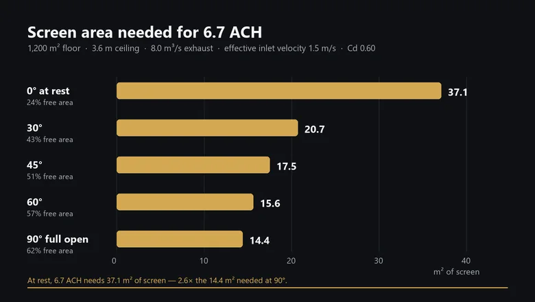
Take a 1,200 m² office floor, 3.6 m ceiling, so 4,320 m³ of volume, with 288 m² of kinetic screen on two 40 m elevations. Fresh air for 100 occupants at 10 l/s each is 1.0 m³/s, or 0.8 ACH: a very small opening satisfies it. Heat removal is the real duty. At a 40 W/m² internal load the floor produces 48 kW, and holding a 5 K temperature rise between inlet and exhaust needs 8.0 m³/s — 6.7 ACH.
| Duty | Target | Airflow | ACH | Effective area at 1.5 m/s | Screen area at rest |
|---|---|---|---|---|---|
| Air quality only | 10 l/s per person, 100 people | 1.0 m³/s | 0.8 | 0.7 m² | 4.6 m² |
| Heat removal | 48 kW at ΔT 5 K | 8.0 m³/s | 6.7 | 5.3 m² | 37.1 m² |
| Night purge | 10 ACH for 8 hours | 12.0 m³/s | 10.0 | 8.0 m² | 55.6 m² |
Read the last column and the practical rule appears: if the design is fixed on the rest position, the heat-removal duty needs 12.9% of the elevation given over to ventilation screen; if the design can rely on the blades opening, it needs 5.0%. The difference is a factor of 2.6, and it is the single largest lever on how much facade you spend on ventilation. A project that cannot guarantee the blades will be open — because the same screen is doing rain defence or glare control — has to buy the larger area.
Two sanity checks keep the number honest. First, capacity is not comfort: 8 m³/s through a 5 m² effective area is a 1.5 m/s jet at the inlet, and it must decay to below 0.8 m/s at 1.1 m above the floor, which sets the ceiling height and the inlet geometry. Second, exhaust must match supply: an inlet-only design pressurises the floor and the flow collapses to whatever leaks out. Provide at least 80% of the inlet area on the leeward or high level, and keep the two paths at least 6 m apart in plan so the air crosses the occupied zone rather than short-circuiting.
Why is outdoor temperature, not free area, the real limit at 45 °C?
Because ventilation can only cool a space while the outdoor air is colder than the heat the space is producing. The balance point is easy to calculate: outdoor temperature at which the ventilation air removes exactly the internal load. With 48 kW, 8 m³/s and 1.2 kJ/m³·K, the permissible rise is 5 K, so a 26 °C setpoint balances at 31 °C outside.
| Outdoor condition | Heat carried by 8 m³/s | Net effect on a 48 kW floor | Ventilation strategy |
|---|---|---|---|
| 24 °C (Nairobi day) | 19 kW gain | 29 kW of cooling still available | Full natural ventilation, blades open |
| 31 °C (balance point) | 48 kW gain | Zero net cooling | Ventilation for air quality only |
| 35 °C (Gulf shoulder) | 86 kW gain | 38 kW of extra load | Sealed, mechanical cooling |
| 45 °C (Gulf peak) | 182 kW gain | 134 kW of extra load, 3.8× internal | Sealed; blades for shading only |
| 28 °C night (Gulf winter) | 19 kW gain | Purge of stored heat | Night purge at 10 ACH |
This is the honest answer to the question every Gulf client asks about natural ventilation. Through July and August the outdoor air at 45 °C carries 182 kW of heat into a floor that only generates 48 kW, so opening the facade makes the building four times worse. The facade is still doing its job — shading, glare control, rain protection — but the ventilation dampers stay closed and the chillers run. Natural ventilation earns its keep in the shoulder months, at night, and in East African highland climates where the daily maximum sits near 26 °C all year.
Night purge is where the same screen pays back in hot climates. Concrete and screed store roughly 200–400 kJ/m²·K; a 1,200 m² slab therefore holds 240–480 MJ per kelvin, and 10 ACH for eight hours with a 6 K night depression can remove 60–120 MJ — enough to delay the morning chiller start by two to three hours. The blades must be able to open at night without a control signal, which is exactly what a passive screen does, and the facade must be secure and rain-tight while open, which is the detail that decides whether the strategy is approved.
How do you detail a mixed-mode facade with kinetic louvres?
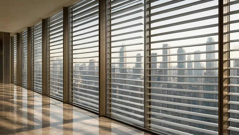
Mixed mode means the floor has both natural and mechanical paths, and the design work is in the changeover rather than in either path alone. Four modes cover a year, and each one needs a defined trigger, a defined blade position and a defined damper position. Without that table, the BMS and the passive blades argue.
| Mode | Trigger | Blades | Dampers / plant | Target |
|---|---|---|---|---|
| M0 Sealed | Outdoor above 31 °C or below 18 °C; wind above 20 m/s | Modulated for shading | Closed; chillers or heating on | Design setpoint, minimum fresh air by AHU |
| M1 Natural | Outdoor 20–31 °C, wind 0.9–8 m/s | Follow wind, 30–60° | Open; chillers off | 6–8 ACH, 26 °C |
| M2 Mixed | Outdoor 28–31 °C with high internal load | 45° | Open, plus fan-assisted extract | Fresh air plus 40–60% cooling |
| M3 Night purge | Outdoor below 24 °C, 22:00–06:00, unoccupied | 90° | Open; plant off | 10 ACH, slab cooled |
| M4 Storm / fire | Wind above 20 m/s, or fire alarm | Feathered or closed | Closed; smoke extract by dedicated system | Watertight, compartment sealed |
Three details decide whether the table is achievable. First, the ventilation opening and the weatherseal must be separate: the kinetic screen modulates airflow, but the air barrier, the vapour line and the drainage plane belong to the glazed wall behind it. Trying to make one louvre do both gives a screen that is neither watertight nor controllable. Second, a passive blade cannot be commanded, so any mode that requires a defined closed position — M0, M4, smoke control — needs a motorised zone damper or a motorised variant. Third, if the facade is part of the smoke ventilation strategy, it becomes a smoke and heat exhaust ventilator and must be certified to EN 12101-2 with its own actuators, power supply and control; a passive louvre cannot be credited.
How do you keep dust and sand out in Gulf projects?
You do not filter the facade; you manage the particle sizes and the pressure. A louvre screen stops coarse sand above roughly 100 µm when the blades are at rest and overlap, and it stops almost nothing below 10 µm. Gulf ambient PM10 runs at 80–150 µg/m³ through the year and passes 500–1,500 µg/m³ during a shamal, so a screen alone will not keep a floor clean — and a filter that is added to fix it will take most of the pressure budget.
| Particle size | Behaviour | What stops it | Design consequence |
|---|---|---|---|
| Coarse sand, >100 µm | Saltates, settles on ledges | Blade overlap at rest, 15–25 mm | Keep rest angle closed enough to overlap |
| PM10, 10–100 µm | Follows the air, deposits in plenums | ISO 16890 ePM10 ≥50% filter | Filter box with accessible face |
| PM2.5, <10 µm | Stays airborne, reaches the room | ePM2.5 ≥50% or ePM1 filter | Higher pressure drop; recalculate ACH |
Keep the inlet plenum velocity below 1.5 m/s so dust drops out rather than being carried in, slope horizontal surfaces to drain and clean, and put the filter where a technician can reach it from the floor rather than from a cradle. In mechanical mode a small positive pressure of 5–10 Pa keeps dust out of the envelope; in natural mode that pressure does not exist, which is the trade-off to state openly in the design report. Maintenance follows from the same logic: clean the plenum and change filters on a 6-month cycle in C4/C5 air, 12 months inland, and inspect blade edges and pivot seals at the same visit.
What acoustic penalty comes with natural ventilation openings?
A large one, and it has to be designed rather than discovered. A sealed unitised glazing line with a 42 dB Rw gives a composite reduction that collapses as soon as an open area appears: 1% open gives about 20 dB, 5% gives 13 dB, 10% gives 10 dB. Since 5 m² of effective opening on a 288 m² elevation is 1.7%, a typical natural ventilation design lands between 15 and 20 dB — fine on a quiet site, unacceptable beside a motorway.
| Open fraction of facade | Composite R with Rw 42 sealed line | Subjective effect | Where it is acceptable |
|---|---|---|---|
| 0.5% | 23 dB | Quiet, traffic audible | Urban sites up to 65 dB(A) outside |
| 1% | 20 dB | Noticeable traffic noise | Suburban, low-speed roads |
| 2% | 17 dB | Conversation at raised voice | Residential set back from the road |
| 5% | 13 dB | Road noise dominates | Courtyards and quiet elevations only |
| 10% | 10 dB | Open-window condition | Not acceptable for offices near traffic |
Three moves recover most of the loss. Put the opening on the quiet elevation and let the air cross the floor, which is free acoustically. Add a lined plenum or an acoustic baffle behind the screen: a 600 mm deep, 50 mm lined path gives 8–12 dB of additional attenuation with a pressure penalty of 2–4 Pa, which is affordable at 3 m/s and not at 1.5 m/s. And accept a lower ventilation rate at peak noise hours, using the thermal mass to ride through — the same passive logic that makes the screen work. The full acoustic treatment of the screen itself, including self-noise and absorptive blades, is in the acoustics article.
How is ventilation performance commissioned and verified?
By measuring air change, not by inspecting blade angles. The reference methods are tracer gas decay to ISO 12569 and ASTM E741, and the acceptance criterion should be written before the test: typically ±20% of the design ACH in each mode, measured on three separate days to cover the wind range.
| Test | Method | What it proves | Acceptance |
|---|---|---|---|
| Tracer gas decay | ISO 12569 / ASTM E741, SF6 or CO2 | Actual ACH in each mode | ±20% of design; ACH = ln(C0/C1)×60/Δt |
| Blade activation | Variable-speed fan, three runs | Opening at ≤0.9 m/s, return below 0.6 m/s | Hysteresis ≤0.2 m/s, repeatability ±0.05 |
| CFD model | EN 16798-7, 5-point grid | Air speed at 1.1 m, short-circuit risk | ≤0.8 m/s occupied, ≥6 m path separation |
| Smoke test | EN 12101-2 if credited | Extract rate, opening time | Per approved strategy |
| Thermal survey | IR camera at handover | No unintended leakage path | No anomaly at junctions |
The arithmetic is simple enough to check on site. A decay from 1,000 ppm to 500 ppm in six minutes is ln(2)×60/6 = 6.9 ACH; the same decay in twelve minutes is 3.5 ACH. If the measured value is half the design figure, the cause is almost always resistance that was not in the model — mesh, a closed damper, a fire damper stuck shut — rather than the screen. Commission in the shoulder season, when the wind is in the design range, and repeat in summer so the client sees the sealed-mode performance as well.
What should the ventilation clause in the specification say?
Eight lines, written as measurable performance rather than as a description of hardware. Each one maps to a test above, and each one closes a substitution route.
- Free area: 24% ±2 at rest and 62% ±3 at 90°, measured on a 1.2 m × 1.2 m sample, with frame and mesh in place.
- Effective area: state Cd used in the calculation and verify it by tracer gas, not by geometry alone.
- Air change: 6.7 ACH in M1 at 3 m/s and 10 ACH in M3 at 90°, each ±20% on site.
- Activation: blades start at ≤0.9 m/s, return below 0.6 m/s, hysteresis ≤0.2 m/s, proven three times.
- Comfort: ≤0.8 m/s at 1.1 m in the occupied zone, draught rate ≤20%, per ASHRAE 55 and EN 16798-3.
- Dust: inlet plenum ≤1.5 m/s, ISO 16890 ePM10 ≥50% filter, filter face accessible from the floor.
- Acoustics: composite R ≥15 dB in M1 and ≥40 dB in M0, with the open fraction stated.
- Safety: smoke control, if credited, certified to EN 12101-2 with independent power; fire compartmentation to EN 13501-1 maintained at every penetration.
Key takeaways
- Free area is 24% at rest and 62% at 90° — but effective area, after Cd of 0.5–0.62 and mesh losses, is 12–38 m² per 100 m² of screen.
- Air quality needs 0.8 ACH; heat removal needs 6.7 ACH. Only the second one sizes the facade.
- At 0.9 m/s the wind delivers 0.5 Pa and less than 0.9 m/s through the opening — the blade activates exactly when wind stops being a useful driver.
- Natural ventilation balances at about 31 °C outside for a 48 kW floor; at 45 °C it adds 182 kW, so Gulf summers must run sealed.
- Designing on the rest position costs 2.6× the screen area of designing at 90°: 37.1 m² against 14.4 m² for the same 6.7 ACH.
- Openings that give 6.7 ACH cost 13–17 dB of facade sound reduction; a lined plenum recovers 8–12 dB for 2–4 Pa.
- Commission by tracer gas to ISO 12569, not by inspecting blade angles; ±20% of design ACH is the acceptance line.
Frequently asked questions
Can a kinetic facade provide natural ventilation without fans?
Yes, on floors where the outdoor air stays below about 31 °C and the wind or stack provides pressure. INDECO blades open from 0.9 m/s and give up to 62% free area, enough for six to eight air changes. Above the balance point you still need mechanical cooling, but not necessarily mechanical fresh air.
How many air changes can a kinetic louvre facade deliver?
Six to eight air changes per hour is the practical design range for a 1,200 square metre floor plate, using about 5% of the elevation as ventilation screen at full opening. Higher rates are physically possible but cost comfort and acoustic performance, and above ten air changes the benefit is small.
Does natural ventilation work in 45 °C Gulf heat?
Not for cooling. At 45 °C outside, ventilating a 26 °C floor adds 182 kilowatts of heat against an internal load of 48, so the facade stays sealed and the chillers run. The screen still earns its cost through shading, and night purge works in the cooler months.
How much facade area should be given to ventilation openings?
Budget 5% of the elevation if the blades will be open at 90° during occupied hours, or 13% if the design must work with the blades at rest. For a 288 square metre elevation that is 14.4 against 37.1 square metres for the same 6.7 air changes.
Will opening the facade let in traffic noise and dust?
Yes, and both must be designed for. An opening equal to 2% of the facade drops sound reduction from 42 to about 17 dB, and a louvre screen stops coarse sand but not PM10. Use a lined plenum, an ePM10 filter and the quiet elevation for inlets.
Designing a naturally ventilated facade?
Send us the floor plate, the orientation and the local wind and temperature data. We will return a free-area schedule, an air-change calculation at three wind speeds and a mixed-mode mode table for your climate.