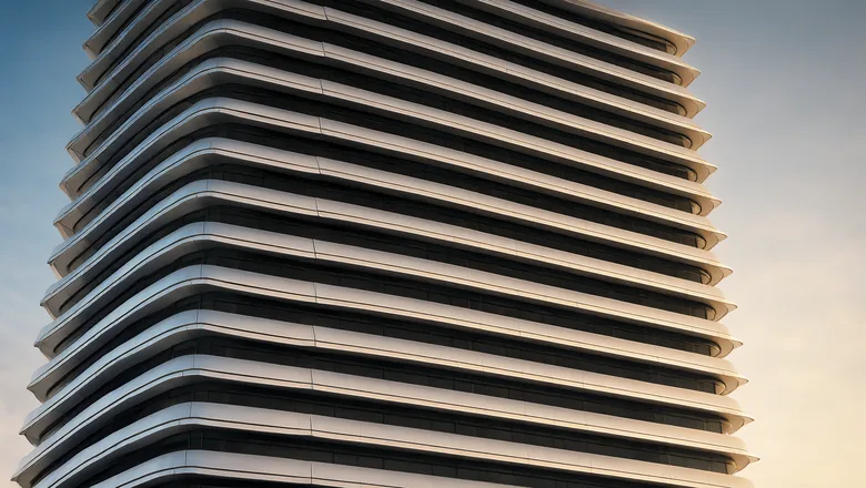
Most kinetic facade specifications describe the system and leave the blade to a single line: “aluminium louvre blade, 150 mm, anodised”. That line hides the decision that governs almost everything downstream — the profile. The profile fixes the open area you get at rest, the wind torque the pivot has to carry at 45 m/s, the spring rate that makes the blade respond at 0.9 m/s, the amount of water a hollow chamber can hold, and a good part of the cost per square metre.
This article works through blade geometry from first principles: the four profile families we extrude, how chord and pitch together hold static solidity near 80%, why a closed cell is worth its extra cost in torsion, how activation torque is balanced against a 2,500:1 wind range, which tolerances belong in the tender, and how the detail changes at 45 °C in C4 and C5 air. It follows the wind-load design range, the movement families and the installation sequence.
What is a kinetic louvre blade profile and what does it control?
A blade profile is the extruded cross-section that runs the full length of a module. In a kinetic facade — also called a dynamic facade, moving louver screen or wind-responsive louvre system — every blade is a beam spanning between module uprights, carried on a pivot at each end and returned by a spring. The section therefore has to do four jobs: present a shading surface, resist bending along a 4.0 m span, resist twisting about its own axis, and give the pivot and spring somewhere precise to sit.
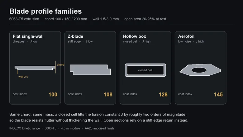
Four families cover almost every project. The flat single-wall blade is a plate with small edge returns; it is the cheapest metre of extrusion and the easiest to anodise, but its torsion constant is low. The Z-blade folds the plate into a shallow Z, which puts a stiff flange where the wind moment is highest and cuts visible flutter. The hollow box closes the section into one or two cells, which raises torsional stiffness by two orders of magnitude and gives the pivot a natural housing. The aerofoil rounds the leading and trailing edges, reduces flow separation and self-noise, and is the profile we use where the screen sits close to occupied space.
The one number that ties them together is solidity. Pitch is chosen so that the screen is about 80% solid at rest whatever the chord: 100 mm blades on a 125 mm pitch, 150 mm on 190 mm, 200 mm on 250 mm. All three land at 20–21% open. What changes with chord is not the open area but the depth of the shadow and the granularity of the view through the screen — the point made in the glare and daylight article.
Which blade chord should you specify: 100, 150 or 200 mm?
Chord is a shading and structure decision, not a free choice of appearance. A wider blade shades a deeper band of facade for the same pitch, carries more wind load per blade, and reduces the number of moving parts per square metre — which is where the maintenance saving comes from. The table below is the range we build and the numbers that follow from it at a 4.0 m module.
| Blade chord | Pitch | Blades per m² | Open at rest | Blade mass | Screen mass | Load per blade at 45 m/s |
|---|---|---|---|---|---|---|
| 100 mm | 125 mm | 8.0 | 20% | 1.35 kg/m | 10.8 kg/m² | 0.6 kN |
| 150 mm | 190 mm | 5.3 | 21% | 1.95 kg/m | 10.3 kg/m² | 0.9 kN |
| 200 mm | 250 mm | 4.0 | 20% | 2.60 kg/m | 10.4 kg/m² | 1.2 kN |
Read the last two columns together and the engineering case becomes clear. Screen mass stays inside 10.3–10.8 kg/m² across the whole range, because a wider blade is also a thicker one; what changes is concentration. A 200 mm blade puts twice the load of a 100 mm blade into one pivot, so the pivot, the module upright and the anchor all grow, while the number of pivots, springs and blade ends to inspect falls by half. On a 10,000 m² elevation that is 80,000 pivot assemblies against 40,000 — the difference between a maintenance regime that closes and one that does not.
How does torsional stiffness decide whether a blade flutters?
Torsion, not bending, is what makes a louvre blade feel cheap. A blade is loaded eccentrically: wind pressure acts on the face, the centre of pressure sits ahead of the pivot axis, and the resulting torque twists the section along its length. If the section is open, the twist is large, the blade tip lags the drive end, and in gusty wind the blade oscillates about its axis — the flutter that shows up as a visible shimmer and, in time, as fretting at the pivot.
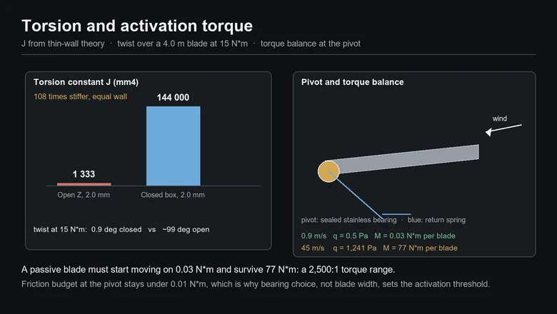
Thin-wall theory gives the comparison directly. For an open section, J is the sum of bt³/3 over the flats; for a closed cell, J = 4A²/∮(ds/t). Take a 200 mm blade, 2.0 mm wall, 500 mm developed perimeter. The open profile gives about 1,333 mm⁴; the closed cell, with an enclosed area near 3,000 mm², gives about 144,000 mm⁴. That is a factor of 108 on identical wall thickness and near-identical mass.
| Section | J (mm⁴) | Twist over 4.0 m at 15 N·m | Practical consequence |
|---|---|---|---|
| Open Z, 2.0 mm | 1,333 | about 99° | Visibly soft; needs a stiff edge return and a short blade |
| Closed box, 2.0 mm | 144,000 | about 0.9° | Blade behaves as a rigid body; flutter disappears |
Two practical notes follow. First, the closed cell is what allows a 200 mm blade to run a 4.0 m span without intermediate supports, and it is why our passive range can use one pivot per end rather than a centre carrier. Second, torsion is sensitive to the third power of wall thickness in an open section but only linearly in a closed one: thickening an open profile from 2.0 to 3.0 mm buys 3.4×, while closing the section buys 108×. When a blade is fluttering, close the section before you add metal.
How is activation torque balanced so the screen moves at 0.9 m/s?
By keeping friction and spring preload an order of magnitude below the wind torque at the activation threshold. That sounds obvious and is where most passive designs fail. At 0.9 m/s the dynamic pressure is only 0.5 Pa (q = 0.613 V²), so a 4.0 m × 200 mm blade with a drag coefficient near 1.2 sees about 0.5 N, and with the centre of pressure 65 mm ahead of the pivot that is roughly 0.03 N·m of driving torque.
| Condition | Dynamic pressure | Force on one 4.0 m blade | Pivot torque |
|---|---|---|---|
| Activation, 0.9 m/s | 0.5 Pa | 0.5 N | 0.03 N·m |
| Design service wind, 45 m/s | 1,241 Pa | 1,190 N | 77 N·m |
A 2,500:1 torque range is the whole design problem in one line. The pivot has to release at 0.03 N·m, which caps bearing friction near 0.01 N·m per blade — the reason the range uses sealed stainless bearings and a dry, low-friction bearing surface rather than a plain bush. At the other end the same pivot carries 77 N·m without deformation, which sets the shaft diameter, the bearing size and the wall thickness around the bore.
The return spring is the second half of the balance. Its preload must be low enough that the blade starts at 0.9 m/s and high enough that the blade returns to its rest angle when the wind drops, against the same friction. In practice the spring is sized on the return condition, not the opening condition, and given a small counterweight or a two-rate characteristic where the rest angle has to be held accurately for shading. Above 45 m/s the blade should be free to feather rather than fight the wind; a passive system does this automatically, which is one reason the passive range reaches 99.8% availability without a control system.
Which extrusion tolerances and wall thicknesses belong in the specification?
Put the tolerances in the tender, or accept whatever the die gives you. A kinetic blade is a moving part with a bore, a cut length and a mating face, so it needs precision-profile tolerances rather than standard mill tolerances. The reference set we work to is EN 755-9 for extruded profiles and EN 12020-2 for precision profiles, with ASTM B221 as the US equivalent.
| Parameter | Tender value | Why it matters on a moving blade |
|---|---|---|
| Wall thickness | 2.0 mm nominal, ±0.10 mm | Sets torsion, screw purchase and anodising current density |
| Chord and depth | ±0.5 mm | Visible pitch variation along an elevation |
| Twist | ≤1.0 mm/m | Blade sits at an angle that differs end to end |
| Straightness | ≤1.0 mm/m | Shows as a waving line across 4.0 m |
| Cut length | ±1.0 mm | End clearance to the module upright |
| Pivot bore position | ±0.2 mm | Bearing alignment and friction |
| Edge radius before finishing | ≥0.5 mm | Anodic film cracks and burns on a sharp arris |
Wall thickness deserves a separate word because it is where value engineering usually goes wrong. Dropping from 2.0 to 1.5 mm saves roughly 12–15% of extrusion cost and costs about 42% of the open section’s bending stiffness (∝ t³). On a closed cell the penalty is smaller but the bearing housing and the screw flanks get thin, and anodising thinner walls at the same current density runs hotter. Our default is 2.0 mm on 100 and 150 mm blades and 2.5 mm on the 200 mm blade, where the pivot bore and the 45 m/s moment both live.
How do you detail a hollow profile for water, dust and drainage?
Drill it, orient it, and never seal it. A hollow blade is a small tank: a 200 mm cell with about 3,000 mm² of enclosed area holds 3 litres per metre, or 12 litres in a 4.0 m blade. If condensate or wind-driven ingress collects in a sealed chamber, it sits against the inside face, produces white rust, and in a Gulf summer expands as it heats. The detail that prevents this is a pair of 6 mm weep holes at the lowest point of each chamber in every blade, with the blade oriented so the holes are down at rest.
- Two holes per chamber, 6 mm minimum: one at each end of the lowest face, so a blade that is slightly out of level still drains.
- Debris screen: a stainless or polymer mesh over the holes that passes water but not the dust which turns to mud in the Gulf.
- No foam filling: filling a hollow blade to stop drumming traps water and destroys the drainage path; use a damping tape or a divided cell instead.
- Rack marks away from sight: anodising racks mark the profile, so specify the racking face on the hidden edge.
- Through-rinse: hollow sections must be rinsed through after anodising, or acid remains in the cell and shows as a stain months later.
- End caps that breathe: caps should close the section visually without sealing it; a fully sealed cap converts the blade into a pressure vessel.
How does the finish interact with profile geometry?
More than most specifications admit. Anodising grows the film out of the metal, so every edge, every inside corner and every hollow cell changes the current distribution. On a sharp arris the film grows thick and can craze; in a deep narrow cell the electrolyte exchanges poorly and the coating runs thin. The range is finished AA25 — 5–20 µm oxide, 200–500 HV, ΔE ≤ 2.5 — through our anodizing partner in Guangdong, and the profile is designed for it rather than corrected afterwards.
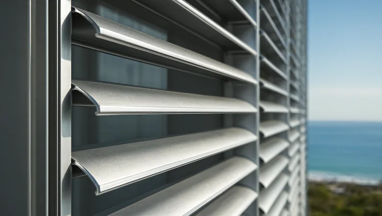
Three rules keep the finish consistent. Break every external edge to at least 0.5 mm and every internal corner to a radius the electrolyte can reach. Keep the visible face vertical during racking so the film builds evenly. And treat colour as a batch property: anodised aluminium is not paint, so a ΔE of 2.5 between batches is realistic and should be written as the acceptance limit, with blades for one elevation ordered as a single batch. Where a project wants a specific RAL colour or a metallic effect, the alternative is 70% PVDF at 25 µm to AAMA 2605, which covers the profile geometry uniformly but adds a coating that can chip on a moving edge.
What do the profiles cost, and where is the value?
Profile choice moves the blade line by roughly 45% and the whole screen by 8–12%. The index below is against a flat single-wall blade at 100, and covers extrusion, anodising and cutting, excluding the pivot and the module frame.
| Profile | Cost index | Die cost (USD) | Where the money goes |
|---|---|---|---|
| Flat single-wall | 100 | 1,200–1,800 | Simple die, fast run, easy racking |
| Z-blade | 108 | 1,500–2,200 | One extra fold, stiffer edge, same wall |
| Hollow box | 128 | 2,000–3,200 | Bridge die, two cells, through-rinse, weep drilling |
| Aerofoil | 145 | 2,600–4,000 | Curved surfaces, tighter tolerance, polishing before anodising |
Four adders are worth carrying in the budget: an extra cavity +8–12%, drilled drainage and end machining +2–4%, precision tolerance +3–6%, and a colour outside the standard anodising range +5–10% with a minimum run of 300–500 kg per die. Where the volume is small, the die is the whole argument: a 400 m² feature wall cannot absorb a USD 4,000 aerofoil die, so it uses a standard box profile. Where the elevation runs to 10,000 m², the die is noise and the torsion is worth paying for. The wider budget structure is set out in the cost and value-engineering article.
How do profiles perform at 45 °C and in C4/C5 coastal air?
Thermal movement is modest and must still be given somewhere to go. Aluminium expands at 23 µm/m·K, so a 4.0 m blade grows 5.1 mm over a 55 K swing — from a 20 °C night to a 75 °C blade face, which is what a dark anodised blade reaches at 45 °C ambient in direct sun. Keep at least 10 mm of clearance at each blade end, and never let a blade end bear on the module upright at one end only.
| Condition | Effect on the blade | Detail that answers it |
|---|---|---|
| 45 °C ambient, 75–80 °C blade face | 5.1 mm growth over 4.0 m | ≥10 mm end clearance, slotted pivot bracket |
| Dust and sand | Deposits in hollow cells, wears pivot seals | Weep holes with mesh, sealed bearings, 12-month clean |
| ISO 9223 C4 coastal | Chloride attack at fixings and cut ends | A4 stainless pivots, EPDM isolation, cut ends sealed |
| ISO 9223 C5 splash zone | Faster attack, more frequent cleaning | A4 throughout, stainless trays, 6-month inspection |
| Fire, EN 13501-1 | Aluminium alloy is non-combustible (A1/A2) | No combustible core, intumescent-free detailing |
Two details do most of the work in these climates. The first is isolation: an EPDM or polymer separator between the aluminium blade and every stainless fixing, because aluminium-to-stainless contact in a wet, chloride-bearing cavity is a corrosion cell with a small anode and a large cathode. The second is access: every pivot, spring and weep hole has to be reachable from a cradle, which is why the 200 mm blade with half the components is often the cheaper choice over 25 years even at a higher price per metre. The inspection intervals and wear points are in the maintenance article.
What should the blade clause in the specification say?
Eight lines cover it, and they are the lines that prevent a substitution later. Write them as performance requirements with a submittal obligation rather than as a product description, and ask for the extrusion drawing, the mill certificate and the anodising batch record with the sample.
- Alloy and temper: 6063-T5 to EN 755-9 / ASTM B221, with mill certificate to EN 10204 3.1.
- Profile: chord, pitch, number of cells and wall thickness, with a dimensioned extrusion drawing for approval.
- Torsion: calculated J and the twist at the design moment over the full span, stated in degrees.
- Activation: blade starts to open at or below 0.9 m/s and returns to rest below 0.6 m/s, proven on a mock-up.
- Structure: no permanent deformation at 1.5× the 45 m/s design pressure, with the calculation submitted.
- Tolerances: wall ±0.10 mm, twist and straightness ≤1.0 mm/m, bore position ±0.2 mm.
- Finish: AA25 anodising, 5–20 µm, 200–500 HV, ΔE ≤ 2.5, single batch per elevation.
- Drainage and access: two 6 mm weep holes per chamber per blade, and every pivot reachable for service.
Key takeaways
- Profile, not chord alone, decides shading, stiffness, activation and cost; specify the section, not just the width.
- Pitch scales with chord, so static solidity stays near 80% (20–21% open) across 100, 150 and 200 mm blades.
- A closed cell is about 108× stiffer in torsion than an open profile of equal wall: 0.9° of twist against 99° at 15 N·m.
- Activation at 0.9 m/s needs only 0.03 N·m, while 45 m/s delivers 77 N·m — a 2,500:1 range that bearing friction decides.
- Hollow blades need two 6 mm weep holes per chamber: a sealed 200 mm cell can hold 12 litres.
- Anodising follows geometry: ≥0.5 mm edge radius, even racking, and a single batch per elevation to hold ΔE ≤ 2.5.
- Profile choice moves the blade line by about 45% but the whole screen by only 8–12% — spend it where torsion and access pay back.
Frequently asked questions
Which blade profile is best for a kinetic facade?
For most elevations a closed box profile is the best balance: it is about 108 times stiffer in torsion than an open section of equal wall, it houses the pivot cleanly, and it costs roughly 128 against 100 for a flat blade. Use aerofoil sections only where the screen sits close to occupied space.
Is a hollow or an open blade better?
Hollow, wherever the span exceeds about 2.5 metres or the wind design speed exceeds 35 metres per second. An open Z-blade is cheaper and adequate for short feature screens, but it twists visibly and needs a stiff edge return to avoid flutter in gusty conditions.
How thick should a kinetic louvre blade wall be?
Two millimetres is our default for 100 and 150 millimetre chords, and 2.5 millimetres for a 200 millimetre blade, because the pivot bore and the 45 metre per second moment both concentrate there. Dropping to 1.5 millimetres saves 12 to 15 percent of extrusion cost but removes about 42 percent of bending stiffness.
Why does the blade need 0.9 m/s of wind to start moving?
Because that is where the driving torque first exceeds friction and spring preload. At 0.9 metres per second the wind applies only about 0.03 newton-metres to a four metre blade, so pivot friction must stay near 0.01 newton-metres. Sealed stainless bearings, not blade width, set that threshold.
Can kinetic blades be anodised in any colour?
Anodising colours are limited to the natural oxide palette plus dyes and electrolytic bronzes, and they shift with alloy and batch. Specify AA25 with a colour range and a delta-E limit of 2.5, order one elevation as a single batch, and use 70 percent PVDF where an exact RAL match is mandatory.
Specifying kinetic blades?
Send us the elevation, the design wind speed and the exposure category. We will return a blade drawing, the torsion calculation and a costed option across two profiles within five working days.