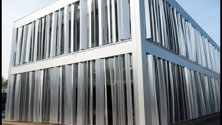
A specification that says “tested to EN 13830 and ASTM E331” describes a static wall. It proves that a fixed assembly keeps water out at 750 Pa and survives a structural hold, but it says nothing about a blade that moves 30 times a day for 25 years. Kinetic facade testing exists because the mechanism, not the panel, is where the risk sits: pivots wear, springs relax, thresholds drift, and a screen that stood perfectly still during a laboratory test can whistle, flutter or seize on site.
This article sets out what a defensible test programme contains, with the numbers a specifier can put into a tender: cycle counts, water-test blade states, structural hold values, activation tolerances and the acceptance matrix that ties them together. It follows the same 6063-T5 blade family and 4.0 m module used across our kinetic louver facade range, and the wind cases set out in the 45 m/s design guide.
Why does a moving facade need a different test programme?
A static curtain wall is verified in one loaded state. A kinetic facade changes geometry continuously: the same blade is a 24% open screen at rest, a 60% open screen at 90°, and an aerofoil at every angle in between. Testing therefore has to answer three questions a static wall never asks. Does the mechanism still work after a decade of movement? Does the assembly shed water in the positions it will actually occupy? And does the blade stay stable when the wind is strong enough to load it but too weak to move it?
That is why a kinetic package carries two test families. The first is the conventional envelope suite — air, water, structural, thermal, acoustic — applied to the sealed line behind the screen. The second is mechanical: cycling endurance, activation threshold, torque drift and free play. A tender that asks only for the first family leaves every moving part unverified, and the standard curtain wall test sequence will not catch any of those failures.
The split also explains the cost. Envelope tests are routine and comparatively cheap; cycling is the long pole, because a 200,000-cycle protocol runs for months and occupies a rig that cannot be used for anything else.
How many movement cycles must a kinetic facade survive?
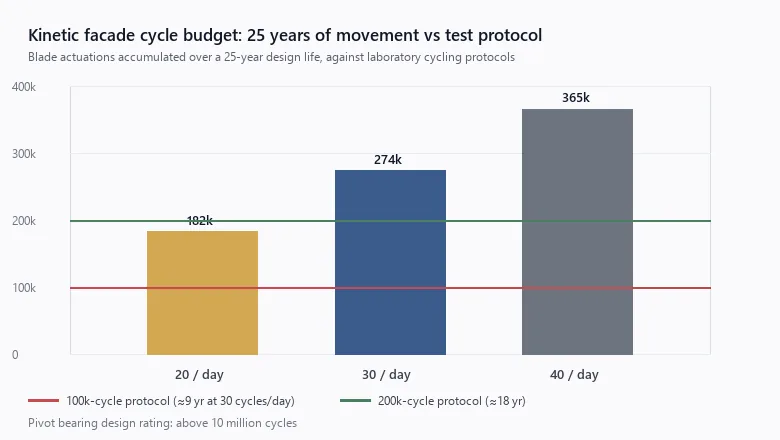
Count the movements, not the years. A passive screen on a coastal site with a steady diurnal breeze typically completes 20 to 40 full strokes a day: opening through the morning as the sea breeze builds, closing again in the evening, plus gust activity. Over a 25-year design life that is 180,000 to 365,000 strokes — far more than the single-figure cycle counts sometimes quoted in specifications.
| Strokes per day | Per year | 25-year total | Protocol that covers it |
|---|---|---|---|
| 20 (sheltered urban site) | 7,300 | 182,500 | 200,000 cycles |
| 30 (typical coastal) | 10,950 | 273,750 | 300,000 cycles |
| 40 (exposed waterfront) | 14,600 | 365,000 | 400,000 cycles |
In practice 100,000 cycles is the floor most specifications use, and it equals about nine years at 30 strokes a day. For a 25-year Gulf or East African project, 200,000 cycles is the defensible number, and exposed waterfront sites justify 300,000 to 400,000. At 40 to 60 cycles per hour on the rig, 200,000 cycles takes 3,300 to 5,000 running hours — five to seven months of continuous operation. That is why cycling is started first and run in parallel with mock-up build and the envelope suite.
Pass criteria matter as much as cycle count. After the run, our protocol requires: no crack in blade, bracket or pivot housing under dye-penetrant inspection of a 10% sample; permanent set no greater than 2 mm over a 4 m blade; activation threshold drift no more than 10%, from 0.9 to 1.0 m/s; pivot friction torque increase no more than 15%; and no cracking or permanent deformation of the EPDM buffers.
The bearing itself is rated above 10 million cycles, so it is rarely the limiting item. The spring, the blade root and the bracket weld fail first, which is where the inspection sample should be concentrated.
How is water penetration tested when the screen stands open?
An open louver screen is a shading device, not a weather barrier, and pretending otherwise produces meaningless test reports. The sealed line behind it — unitised glazing tested to 750 Pa, or a drained backing wall — carries the water-tightness duty. The screen must instead prove three things: that it drains, that water does not carry over onto the inner face, and that the blades do not act as a gutter that floods the cavity during a storm.
The report must state the blade angle, because results are not comparable between states. Three positions are used: rest (24% free area for a 150/190 mm blade set), mid-travel at 45°, and fully open at 90°. A screen that passes at rest and fails at 45° is common, because the inclined blade becomes a catchment surface directing water inward.
| Test | Standard | Target | Blade state |
|---|---|---|---|
| Air permeability | EN 12153, class per EN 12152 | Class A4 at 600 Pa | Rest |
| Static water penetration | ASTM E331 | 750 Pa, 15 min, no uncontrolled penetration | Rest (24% open) |
| Static water penetration | EN 12154 | RE 1200 | Rest |
| Dynamic water penetration | AAMA 501.1 | 240 kPa nozzle, 5 min | Mid-travel 45° |
| Drainage and carry-over | Project method statement | No water on inner face; cavity clears within 5 min | Fully open 90° |
The quantity at stake is larger than vertical rainfall suggests. A 6 m² module in 50 mm/h rain collects about 2.5 L/min on its projected area, and wind-driven rain at 10 m/s drives a substantial share of that flux through a 24% open screen onto the inner blade face. The backing line, not the screen, defines the water class, and the screen's job is to keep that flux away from joints and away from the cavity floor.
How is the facade verified against 45 m/s wind?
A design wind of 45 m/s produces a stagnation pressure of 0.613 × 45² = 1,241 Pa. Applying corner and edge coefficients of 1.7–2.0 and 1.3–1.6 gives local suction of roughly 2.1–2.5 kPa and 1.6–2.0 kPa before any safety factor. We verify this with finite-element analysis across more than 150 load cases — blade angle × wind direction × zone — rather than a single worst-case number, because the critical case for a louver is often a partly open blade at an oblique angle rather than the fully closed screen.
| Check | Method | Target |
|---|---|---|
| Design pressure | q = 0.613 V², 50-year return | 1,241 Pa at 45 m/s |
| Corner zone suction | Cp −1.7 to −2.0 | 2.1–2.5 kPa |
| Edge zone suction | Cp −1.3 to −1.6 | 1.6–2.0 kPa |
| Structural test | ASTM E330 | 4.5 kPa design, 6.75 kPa at 1.5× |
| Blade clearance | FEA plus physical deflection | ≥10 mm between adjacent blades at design pressure |
| Anchor proof load | 1.5× design, 10 s hold | No slip, no permanent deformation |
The 4.5 kPa figure is project-specific, not generic. It is the structural class used on the Gulf Waterfront Commercial Tower, where the 45 m/s service wind and corner suction combine. A 26.9 m/s East African site such as the East Africa CBD Tower in Nairobi needs about a third of that pressure — 0.44 kPa — and the same test sequence at a lower hold value. Fixing one pressure for every project either over-designs Nairobi or under-tests Doha.
How is the 0.9 m/s activation threshold proven?
“Activates below 0.9 m/s” — about 2 mph — is a mechanical property, and it is measured, not asserted. The mock-up is placed in front of a calibrated fan array or in a boundary-layer wind tunnel, with anemometers at facade face height, and wind is ramped from 0.3 to 5 m/s while blade angle is logged.
- Threshold: movement starts at or below 0.9 m/s on three consecutive runs, with 5-minute averaging at the facade face.
- Hysteresis: difference between opening and closing speed no more than 0.2 m/s.
- Repeatability: standard deviation no more than 0.05 m/s across the three runs.
- Temperature: spring rate verified at 45 °C, because a steel spring loses 1–3% of its force over a 50 K rise.
- Dust: 20 cycles after dust conditioning, threshold drift no more than 10%.
Activation is the point where aerodynamic torque first exceeds pivot friction plus spring preload. Both are small numbers, so the threshold is sensitive to build quality: an extra 0.1 N·m of bearing friction can lift activation from 0.9 to 1.3 m/s and make a passive facade look dead in light air. Testing therefore doubles as a production check on bearing fit, spring preload and blade balance — the same variables that govern the self-noise and insertion loss of the screen.
What does a project mock-up contain?
One bay, full height, built with the conditions that actually fail on site. For a 4.0 m module that means 3.0 m wide by 8.0 m high — two stacked modules — plus a 1.5 m corner return, an edge-zone bracket, one movement joint, one drainage outlet and one accessible pivot for inspection. A flat, interior bay with no corner tests nothing that matters.
| Stage | Scope | Duration | Output |
|---|---|---|---|
| 1. Component type test | Blade, pivot, spring, bracket to failure or 10M cycles | 6–10 weeks | Component reports, spring curve |
| 2. System mock-up | Full bay with corner, edge zone, joint, drainage | 4–8 weeks build | Installation method, tolerance check |
| 3. Laboratory suite | Air, water, structural, cycling on the mock-up | 10–20 weeks | Test report with raw curves |
| 4. Site first bay | First installed bay, repeated water and activation checks | 1–2 weeks | Handover benchmark |
Budget 0.5–1.5% of the facade package and 12–20 weeks of programme, with cycling started on day one. That is inexpensive against the alternative: discovering a blade clash, a blocked weep slot or a bracket crack after 4,000 m² is on the building, where every fix carries access, scaffold and programme cost multiplied by the number of affected modules.
Which tests belong in the acceptance matrix?
The matrix below is the minimum we would expect to see signed off before a kinetic facade is released for production. Values are for a 45 °C Gulf project in ISO 9223 C5 air; the same matrix applies elsewhere with the pressure, salt-spray and thermal bands adjusted to the site.
| Test | Standard | Acceptance | When |
|---|---|---|---|
| Air permeability | EN 12153 / EN 12152 | Class A4 at 600 Pa | Mock-up |
| Static water | ASTM E331 | 750 Pa, 15 min, no uncontrolled penetration | Mock-up |
| Dynamic water | AAMA 501.1 | 240 kPa, 5 min, blades at 45° | Mock-up |
| Structural | ASTM E330 | 4.5 kPa design, 6.75 kPa proof | Mock-up |
| Cycling | Project protocol | 200,000 cycles at 40–60 per hour, criteria above | Rig, parallel |
| Activation | Fan array or wind tunnel | ≤0.9 m/s, drift ≤10% after cycling | Rig, before and after |
| Thermal cycling | Project protocol | −5 to +80 °C surface, 30 cycles, no seal failure | Mock-up |
| Salt spray | ISO 9227 | 500–1,000 h (C3), 4,000 h (C5) | Coupons |
| Reaction to fire | EN 13501-1 | A2-s1,d0 | Type test |
Which finish and corrosion tests apply in C4 and C5 air?
Salt-spray hours are a comparative check on the anodising and sealing process, not a service-life prediction. Our AA25 anodised blades carry a 5–20 µm oxide film with 200–500 HV surface hardness and batch colour control to ΔE ≤2.5, tested to ISO 9227 neutral salt spray for 500 to 4,000 hours depending on the ISO 9223 category of the site. For C5 coastal air — Gulf waterfront, Mombasa, Lagos — the 4,000-hour band applies; for C3 inland sites, 500–1,000 hours is proportionate, and specifying 4,000 hours everywhere simply adds cost.
Two further checks matter at 45 °C. Thermal cycling between −5 °C and +80 °C surface temperature over 30 cycles catches differential expansion between aluminium, EPDM and stainless steel, where a Gulf facade can swing 60 K between a shaded night and an afternoon in direct sun. And adhesion after 1,000 hours of condensation catches pretreatment failures that salt spray alone can miss, because a moving blade flexes its coating at the root every time it strokes.
What fails most often — and how is it fixed?
| Symptom | Root cause | Fix |
|---|---|---|
| Blade flutter at 8–15 m/s | Torsional stiffness too low, spring preload mistuned | Aerofoil section, root rib, retuned spring |
| Whistle near 10 m/s | Sharp trailing edge, vortex shedding | Rounded trailing edge, sealed edge cap |
| Water carry-over at 45° | Inclined blade acts as a gutter, weep slots blocked | Repositioned weep slots, inner gutter |
| Threshold drift after cycling | Dust ingress, pivot galling | Sealed bearing, wiper, dry-film lubricant |
| Bracket crack at weld toe | As-welded toe under reversing load | Cast bracket or increased throat, 10M-cycle verification |
| Batch colour shift | Anodising bath variation | ΔE ≤2.5 lot control, single source |
None of these is exotic; each is a known failure mode of moving aluminium in a hot, dusty, saline environment. The argument for testing is purely economic: every one of them is cheaper to find on a mock-up than on a 4,000 m² elevation. The maintenance and inspection schedule picks up the same wear points after handover.
What belongs in the testing clause?
- Blade angle states written into every water test, and reported with the result.
- Cycling protocol: cycle count, rate, stroke, dust conditioning and pass criteria.
- Activation threshold: measurement height, averaging time, hysteresis and test temperature.
- Structural hold values, the 1.5× proof load and the deflection limit.
- Mock-up size, location, corner and edge representation, and retention after test.
- Sample selection: 10% dye-penetrant inspection of blade roots and bracket welds.
- Finish: ISO 9227 hours by ISO 9223 category, plus ΔE and film thickness.
- Reporting: raw curves rather than pass/fail summaries, and retest rules after any design change.
Key takeaways
- A kinetic facade needs mechanical tests — cycling, activation, torque drift — on top of the standard envelope suite, because the moving parts carry the risk.
- At 30 strokes a day over 25 years a blade accumulates about 274,000 cycles; 200,000 is the minimum defensible protocol, and it takes five to seven months on the rig.
- Water tests must state blade angle: rest at 24% open, 45° mid-travel and 90° fully open behave completely differently.
- The 45 m/s case is 1,241 Pa stagnation pressure, 2.1–2.5 kPa at corners, verified by FEA across 150+ cases and a 6.75 kPa proof load.
- Activation below 0.9 m/s is a measured property with a 10% drift allowance after cycling, not a brochure claim.
Frequently asked questions
How long does kinetic facade testing take?
Allow 12 to 20 weeks from mock-up completion. Cycling runs 3,300 to 5,000 hours for a 200,000-cycle protocol, roughly five to seven months of rig time, so it starts first; water, air and structural tests take two to four days; the mock-up itself needs four to eight weeks to build. Finish and salt-spray tests run in parallel.
Does every project need a full mock-up?
Not every project, but any elevation above roughly 500 m², any new blade profile and any site above 40 m/s should have one. A full-size bay with a corner return exposes bracket tolerance, drainage and blade clash before site installation, when correction is still cheap. Standard systems can rely on type-test reports plus a first-bay check.
What is the pass criterion for the activation threshold?
The blades must start moving at or below 0.9 m/s at the facade face, in three repeat runs with a calibrated fan array. After the cycling protocol the threshold may drift by no more than 10%, to 1.0 m/s, and hysteresis between increasing and decreasing wind must stay within 0.2 m/s.
Can an open louver screen pass a 750 Pa water test?
The louver is a shading screen, not the weather barrier. Water testing at 750 Pa to ASTM E331 applies to the sealed assembly behind it — unitised glazing or a drained backing wall — while the screen is assessed for drainage, blade wetting and carry-over. The blade position must be stated in the report.
Which standard governs kinetic facade testing?
There is no single kinetic standard. Projects combine EN 13830 for curtain wall product performance, ASTM E330 for structural pressure, ASTM E331 and AAMA 501.1 for water, EN 12152 and EN 12153 for air, ISO 9227 for salt spray, and a project-specific cycling protocol agreed at tender stage.
Testing a kinetic facade for a live tender?
Send the elevation drawings, the wind study and the blade geometry. We return a test plan mapped to EN 13830 and ASTM, a mock-up scope with programme, and a cycling protocol written into the specification. See the kinetic louver facade range, read how the 45 m/s case is engineered, or talk to our engineering team.