
Wind gets the headlines in facade engineering; earthquakes quietly decide what the joints have to be. In a unitised curtain wall — also written as a unitised glazing system, modular glazing or factory-assembled facade — every panel is already its own structural package, hung from the slab above and interlocked with its neighbours. That arrangement is what makes the difference in a seismic event: instead of the glass and frame fighting the building's sideways movement, the joints absorb it.
This article deals with the number that actually matters, inter-storey drift: how big it gets, where it goes inside a unitised glazed curtain wall, what each joint has to deliver, and how any of this is proven before a single unit ships. It builds on the tolerance chain set out in installation sequencing, the two-stage sealing logic in drainage and pressure equalisation, the batch controls in factory quality control and the standard verification chain in curtain wall performance testing, and it uses the same 45 °C, SBC and Mostadam context applied across our Unitised Glazing guides.
What does seismic drift actually do to a unitised curtain wall?
Inter-storey drift is the difference in horizontal displacement between two adjacent floors. The building frame bends; floor N+1 ends up 60 mm further over than floor N; anything bridging those two floors must accommodate the difference. A curtain wall bridges them by definition, so every storey-high panel inherits that distortion whether it is detailed for it or not.
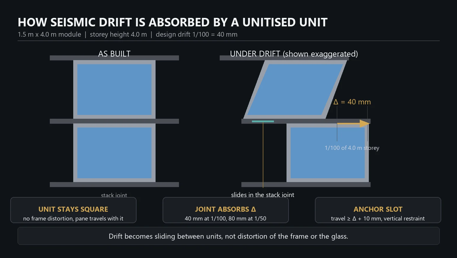
The good news is how that demand is transferred. Because each unit is hung from the slab above and engaged into the head of the unit below in a telescoping stack joint, storey drift shows up as a horizontal slide at that joint — not as a shear across the frame. The panel behaves close to a rigid body: it translates and slightly rotates, and the glass travels with it. This is why well-detailed unitised systems routinely survive drift that would crack glass and glazing gaskets in a continuous stick-built frame.
| Behaviour | Stick-built curtain wall | Unitised curtain wall |
|---|---|---|
| Where drift is absorbed | Racking of the continuous frame plus glass-to-frame clearance | Sliding at the stack joint and in slotted anchors |
| Frame distortion | The rectangular opening becomes a parallelogram | Each unit stays square; the joint changes shape |
| Glass demand | Diagonal change of the opening bear on the pane | Pane moves with the frame; clearance only has to cover residual movement |
| Practical drift capacity | Typically 1/200 to 1/150 before glass contact | 1/100 routinely qualified; 1/50 achievable with a dedicated joint |
| Verification route | Same standards, larger specimen needed to see the effect | Two storeys × two units reproduces real joint kinematics |
Worth stating plainly because it surprises specifiers: the seismic population of the panel themselves is modest. A 6 + 12A + 6 insulated unit in a 1.5 × 4.0 m module weighs around 180 kg of glass in a unit that lands at 265 to 295 kg installed, so the inertia force that produces at 0.3 g is on the order of a tonne — comfortably carried by the same anchors that hold a 4.5 kPa wind load. It is drift, not inertia, that drives the detail.
How much movement does a unitised system have to absorb?
The single most useful habit is to stop talking about ratios and start writing displacement in millimetres per floor. Codes express drift limits as a fraction of storey height, but every joint in a curtain wall is sized in millimetres. On the 4.0 m module used across the INDECO unitised range, the common limits translate like this.
| Limit or target | Drift ratio | Δ over a 4.0 m storey | What it governs |
|---|---|---|---|
| Wind serviceability, occupant comfort | H/500 (0.20%) | 8 mm | Everyday building sway; already inside the normal joint budget |
| EN 1998-1, brittle non-structural | 0.50% | 20 mm | Brittle attachments that cannot slide |
| EN 1998-1, ductile non-structural | 0.75% | 30 mm | Metal components able to yield locally |
| Common unitised qualification level | 1/100 (1.00%) | 40 mm | Standard static racking target, AAMA 501.4/501.6 |
| ASCE 7 / SBC 301 design story drift, Risk Category III | 1.50% | 60 mm | Schools, assembly and high-occupancy buildings |
| ASCE 7 / SBC 301 design story drift, Risk Category I & II | 2.00% | 80 mm | Offices, hotels, housing — the usual commercial case |
| Typical maximum-considered proxy used for testing | 1.4–1.5× design drift | 55–85 mm | The displacement the test rig is commanded to reach |
Compare that with the figure we use in everyday setting out. Serviceability drift at H/500 over the same 4.0 m storey is ±7.2 mm, which is why it can be absorbed inside ordinary bracket adjustment. Seismic design drift is 5.6 to 11 times larger. That difference is the whole argument for a dedicated seismic allowance rather than borrowing headroom from the installation tolerance chain: structure ±20 mm, bracket three-way ±15 mm, joint travel ±6 mm, module ±1.5 mm must all still be there when the floor above has moved 60 mm sideways.
Regional note, because the two markets we engineer for most sit at opposite ends. Several East African markets fall in zones of moderate seismicity where the applicable national codes follow EN 1998-1 or its equivalent, and drift — not lateral force — is normally the governing check for the facade contract. Across much of the Gulf, seismic demand is low and rarely governs, but SBC 301 still requires the drift check to be made and recorded. In those projects the interesting question is whether the joint can satisfy the drift check without giving up the pressure-equalised drainage lines proven for water, and whether a joint that must stay free to move at 45 °C and in ISO 9223 C4–C5 exposure will still be free to move in twenty years.
How does the stack joint absorb storey drift?
Four components carry the movement, and each one needs its own number written into the spec. Get any of them wrong and the capacity of the others is academic, because the stiffest element in the chain attracts the load until something breaks.

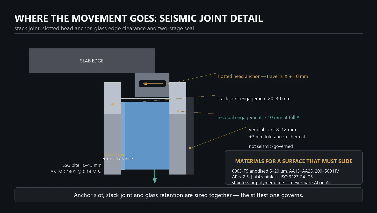
The head anchor is first. It carries the whole unit dead load — 265 to 295 kg for a 6 + 12A + 6 build-up, 370 to 410 kg for 8 + 16A + 12 — while permitting in-plane sliding, so its slot has to be long enough for the drift plus construction tolerance while still restraining the unit vertically and out of plane. Two anchors per unit, one dead and one sliding, is the usual arrangement; a captive washer or clamp plate provides vertical restraint so a strong uplift component cannot unhook the panel.
The second is the stack joint itself, the telescoping interlock between the head of one unit and the sill of the one above. Engagement is typically 20 to 30 mm, with the system detailed so that not less than about 10 mm of that engagement remains at maximum drift. It is the primary sliding surface, and it is where corrosion quietly destroys seismic performance: in C4 and C5 per ISO 9223, aluminium sliding on aluminium will fret and seize. Specify a stainless or engineered polymer glide surface, anodised 6063-T5 framing at 5 to 20 µm (AA15 to AA25, 200–500 HV, ΔE ≤ 2.5) and A4 stainless fasteners, so the joint can still slide after a decade of service.
| Component | Normal design value | Seismic provision | Why |
|---|---|---|---|
| Head anchor slot | ±15 mm three-way adjustment | Travel ≥ Δ + 10 mm, with positive vertical restraint | Anchor must accommodate the drift before it accommodates anything else |
| Stack joint engagement | 20–30 mm nominal | ≥ 10 mm residual engagement at full Δ, low-friction glide | Primary sliding surface; must not lose engagement or seize |
| Glass edge clearance | 3–5 mm each side of the rebate gap | Increased for the relevant drift check, or SSG bite 10–15 mm at 0.14 MPa design | Residual frame distortion must not bring glass onto metal |
| Vertical joint between units | 8–12 mm nominal, ±3 mm working | Unchanged; two-stage seal retained | Adjacent units drift together, so this joint sees tolerance and temperature, not seismic shear |
| Sill / weep path | Pressure-equalised, compartmented per unit | Spill-over must remain sealed at the displaced position | A joint that has slid sideways must still drain |
Glass retention is the third decision. In a conventionally captured (dry-glazed) system the pane is held by gaskets in a rebate, and its survival depends almost entirely on having enough edge clearance and no hard contact. In a structural silicone glazing build-up the pane is bonded to the frame with the silicone taking it all — a material that stays elastic through the whole movement. Our standard units use SSG with a 10 to 15 mm bite controlled to ASTM C1184 and proven at a 0.14 MPa design stress under ASTM C1401, which is why they perform well under racking: there is nothing to pinch. Whichever is used, anti-walk setting blocks and glass retention clips matter more in a seismic zone than anywhere else, because a pane that has migrated across its rebate before the event has already spent all the clearance it had.
The fourth is the plumbing that has to keep working while the building is moving — namely the drainage and compartmentation detailed in our drainage guide, plus the perimeter fire barrier and smoke seal detailed in our fire safety guide. Both are deformation-tolerant systems rather than rigid ones, but both have to be verified at the displaced position: a spandrel barrier that opens a 30 mm gap at maximum drift is worse than no barrier at all.
How is drift compatibility proven in the laboratory?
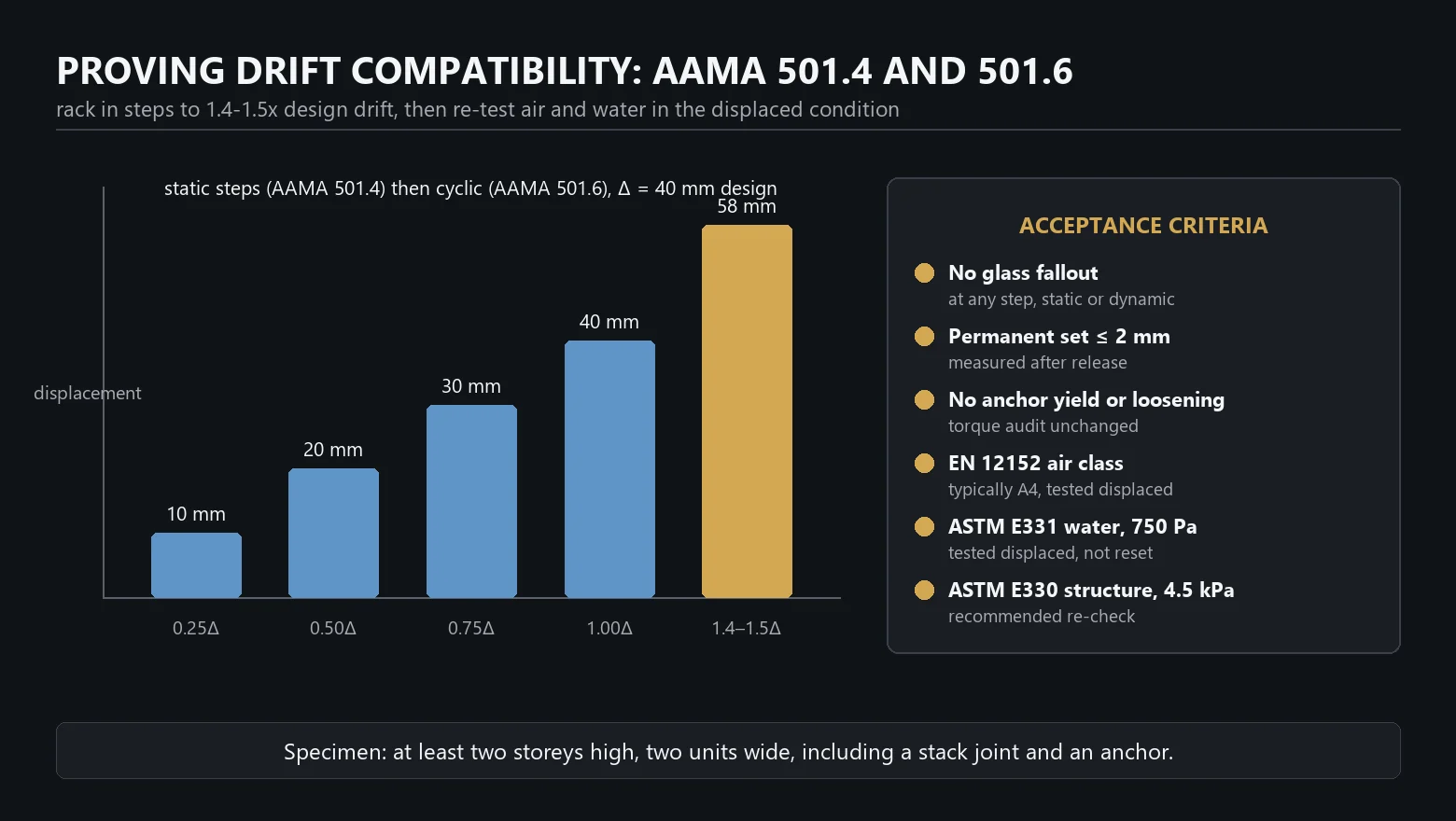
Two AAMA methods are named in almost every serious facade specification, and they answer different questions. AAMA 501.4 is the static test: the specimen is pushed sideways to a series of increasing displacements, held at each one, and inspected for damage and glass fallout before being air- and water-tested. It answers "does anything fall off, and does it still leak". AAMA 501.6 is the dynamic test: the specimen is driven through a cyclic displacement history at earthquake-like rate, which is much closer to what the building actually does, and answers "does the glass stay in during shaking".
| Step | Standard | What is done | Acceptance we write into specs |
|---|---|---|---|
| Specimen | AAMA 501.4 / 501.6 | Two storeys high, at least two units wide, including a corner and a stack joint | Reproduces real joint kinematics; a single unit proves nothing |
| Displacement target | Project drift × factor | 1.4–1.5× the code design storey drift, cyclic | Proxy for the maximum considered earthquake |
| Static racking | AAMA 501.4 | Incremental displacement, hold and inspect at each step | No glass fallout; no permanent deformation > 2 mm; anchors intact |
| Dynamic racking | AAMA 501.6 | Cyclic history at seismic rate to the same peak | No glass fallout; no loss of frame integrity |
| Air permeability after racking | EN 12152 / ASTM E283 | Tested in the displaced condition | Still meets the specified class, typically A4 |
| Water penetration after racking | ASTM E331 | 750 Pa static pressure in the displaced condition | No uncontrolled water past the innermost seal |
| Structural re-check | ASTM E330 | Optional but recommended at 4.5 kPa | Anchors and joint still carry full design wind after the event |
Two points decide whether that test means anything. First, run it on the mock-up, not on a clean specimen — the same assembly that has already been through air, water and thermal cycling, because real joints enter a seismic event already oxidised, dusted and partly compressed. The QC programme that tracks anchor torque, extrusion heat-treatment certificates to EN 10204 3.1, anodising film thickness and SSG batch records is what gives the laboratory specimen its authority; without it the test certifies a hand-made sample rather than a production design.
Second, insist that the post-racking air and water tests are run at the displaced position, not after the rig has been released back to plumb. A joint that reseals when allowed to relax tells you nothing about whether the building was weathertight at three in the morning.
Key takeaways
- Write seismic demand in millimetres per floor, not as a ratio. On a 4.0 m storey: 8 mm at H/500, 40 mm at 1/100, 60 mm at 1.5%, 80 mm at 2%.
- Unitised systems survive racking because drift becomes sliding at the stack joint and in slotted anchors; the unit stays square and the pane travels with it.
- The three most commonly missed items are residual stack-joint engagement (≥ 10 mm at full drift), a genuinely low-friction glide surface for C4–C5 exposure, and post-racking water testing in the displaced condition.
- Structural silicone glazing with a controlled 10–15 mm bite behaves well under racking because there is no glass-to-metal contact to manage.
- Test 1.4–1.5× the code design drift on a two-storey, two-unit-wide mock-up that has already been through its other performance tests.
What should go into the seismic clause of a curtain wall specification?
The shortest useful clause still has eight items. Write them into the curtain wall section rather than leaving them to a performance requirement nobody can enforce, and cross-reference them in the mock-up and QC sections so the same numbers appear in all three places.
- State the demand. Design storey drift in millimetres, floor by floor, with the code and edition named (SBC 301, ASCE 7, EN 1998-1), together with the risk category or importance factor.
- State the test displacement. Typically 1.4 to 1.5 times design drift, written as a number in millimetres so the laboratory cannot reinterpret it.
- Require both methods. AAMA 501.4 static and AAMA 501.6 dynamic, on a specimen at least two storeys high and two units wide, including a stack joint and a representative anchor.
- Set residual-contact criteria. No glass fallout; permanent deformation ≤ 2 mm; no anchor yielding; no fastener loosening beyond the audited installation torque.
- Set an after-the-event weathertightness target. Water penetration ASTM E331 at 750 Pa and air permeability to the specified class (commonly A4 to EN 12152), both tested while the rig remains at maximum displacement.
- Define the joint budget. Stack joint engagement 20–30 mm with ≥ 10 mm residual at full drift; head anchor travel ≥ Δ + 10 mm with positive vertical restraint; remainders of the tolerance chain untouched.
- Define materials for a sliding surface. Anodised 6063-T5 framing at 5–20 µm, AA15–AA25, 200–500 HV and ΔE ≤ 2.5, stainless or engineered polymer glide strips, and A4 stainless fasteners for ISO 9223 C4–C5 exposure.
- Require evidence for the specific unit.Anchor slip tests, extrusions with EN 10204 3.1 certificates, and SSG batch records tied to the mock-up panel IDs — the same traceability that governs Unitised Glazing specifications.
Nothing here is expensive if it is decided before the dies are cut. Retrofitting movement capacity into a system whose joint has already been extruded means new tooling, a new mock-up and a second 12 to 20 week cycle — typically the most expensive change that can be made to a facade package, and one that only becomes visible on site.
Frequently asked questions
How much earthquake movement can a unitised curtain wall take?
A well-detailed unitised system is qualified to a drift of 1/100, which is 40 millimetres over a 4.0 metre storey, and purpose-detailed joints can reach 1/50, or 80 millimetres. What makes that possible is that the drift becomes sliding at the stack joint and in the slotted anchors rather than distortion of the frame.
Why does unitised outperform stick-built curtain wall in an earthquake?
Because each unit stays square. In a stick-built frame the rectangular opening racks into a parallelogram and that distortion bears directly on the glass. In a unitised wall the panel translates and rotates as a unit, so the drift is taken by sliding between neighbours and the pane simply travels with its own frame.
What is the difference between AAMA 501.4 and AAMA 501.6?
AAMA 501.4 is a static racking test: the specimen is pushed to increasing displacements and inspected at each step, then air and water tested. AAMA 501.6 drives the same specimen cyclically at earthquake-like rates, which is closer to real shaking. Serious specifications require both, usually to 1.4 to 1.5 times the code design storey drift.
Does glass fall out of a curtain wall during racking tests?
It should not, and that is the primary acceptance criterion. Structural silicone glazing performs well because there is no glass-to-metal contact to concentrate load, provided the bite of 10 to 15 millimetres and the 0.14 megapascal design stress were verified. Dry-glazed systems depend far more on having sufficient edge clearance left after decades of movement.
Do Gulf projects really need seismic drift testing?
Yes, though rarely as the governing case. SBC 301 requires the drift check to be made and recorded even where seismic demand is low. The real value is that a joint proven able to move also copes with thermal, wind and construction movement without losing weathertightness, where most facade claims start.
Specifying unitised glazing on a seismic project?
Send the storey heights, the applicable code and the design inter-storey drift. We return a joint-by-joint movement budget, stack joint and anchor capacities, the drift displacement for your mock-up, and a test matrix covering AAMA 501.4, AAMA 501.6, ASTM E331 and EN 12152. Start from the unitised glazed curtain wall range, read installation and tolerance chain and performance testing, or talk to our engineering team.