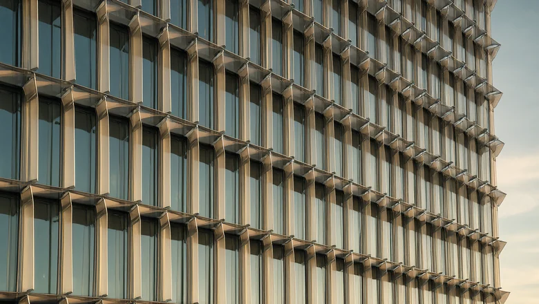
Most kinetic facades are sold as a single skin that replaces the wall. That is rarely what a high-rise needs. A tower still has to be sealed, insulated, acoustic-rated and watertight on every floor, and a 24–62% open louvre screen does none of those jobs. The practical answer is a hybrid: a complete unitised glazed wall doing the sealing, with a separate kinetic screen standing 200–600 mm in front of it doing the shading, the daylight control and the image.
The two systems are individually mature. The difficulty is entirely at the interface — the bracket that crosses the insulation, the cavity that has to drain and ventilate, the load path that must not enter the glass frames, and the question of who signs off the air and water test when a moving screen hides the joints. This guide sets out the three hybrid configurations, the cavity and clearance numbers we design to, a transparent method for calculating the combined SHGC, and the responsibility matrix that keeps the package from falling between two contractors. It follows the wind load article, the passive versus motorised comparison and the unitised drainage article.
What is a hybrid kinetic and unitised glazing facade?
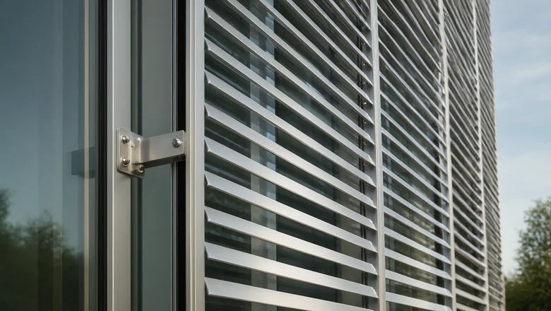
A hybrid facade is two structural and performance systems sharing one elevation, with a deliberate gap between them. The inner system is a factory-sealed unitised wall: 1.5 × 4.0 m modules, 6+12A+6 to 8+16A+12 Low-E units, U ≈ 1.4 W/m²·K, SHGC ≤ 0.22, visible transmittance ≥ 40%, STC 42, 750 Pa water tightness and 4.5 kPa structural wind. The outer system is a kinetic louvre screen: 6063-T5 blades at 100, 150 or 200 mm chord, modules up to 4.0 m, anodised AA25, 24% free area at rest and 62% at 90°.
| Configuration | How it is built | Best for | What to watch |
|---|---|---|---|
| Secondary screen (double skin) | Complete unitised wall, then an independent screen 200–600 mm outside it | New-build towers, large glazed elevations, retrofit | Bracket penetrations, cavity fire barriers, BMU clearance |
| Integrated kinetic bay | Kinetic modules replace vision glass on selected bays inside the same grid | Feature elevations, 20–40% of the facade | Two dead loads (210–250 kg vs 300–450 kg), shared joints, drainage continuity |
| Feature wall plus sealed envelope | Screen confined to podium, canopy or atrium; tower remains fully glazed | Landmark entrances, cultural pavilions | Water shedding at the transition, structural separation |
Configuration two is the one clients ask for and the one that needs the most discipline. An integrated bay puts two products on one setting-out grid, and the kinetic module is lighter than the glazed module it replaces — 210–250 kg against 300–450 kg for a 1.5 × 4.0 m IGU unit. That difference changes the dead-load distribution and the crane plan, and it means the two module types cannot share a bracket family without a specific design check.
Why combine a kinetic screen with unitised glazing instead of choosing one?
Because each system is being asked to do the job it is worst at when used alone. A sealed IGU wall is an excellent barrier and a poor shading device: SHGC 0.22 is good for glass, but 0.22 of a 850 W/m² west elevation is still 187 kW per 1,000 m² of glass. A kinetic screen is an excellent shading device and a poor envelope: it stops sun, not water, and its 24% rest position is an acoustic and air leak by design. Put them together and each keeps its own performance line.
| Layer | Function it owns | INDECO performance data |
|---|---|---|
| Unitised IGU wall | Air, water, thermal, acoustic, fire compartment line | 1.5 × 4.0 m; 6+12A+6 to 8+16A+12; U ≈ 1.4; SHGC ≤ 0.22; VT ≥ 40%; STC 42; 750 Pa; 4.5 kPa; EN 12152 A4; EN 12154 RE 1200 |
| Kinetic screen | Shading, daylight, facade image | 6063-T5; 100/150/200 mm blades; 4.0 m modules; AA25 anodised; 24% free area at rest, 62% at 90° |
| Cavity | Pressure equalisation, drainage, thermal buffer, maintenance | 200–600 mm; 1–2% top and bottom vents; drained sill |
| Brackets | Load transfer, adjustment, movement accommodation | A4 stainless; ±15 mm three-axis; slotted for ±10 mm drift |
The honest limits matter as much as the benefits. If the screened area is below about 15% of the elevation, fixed fins cost 30–45% less, need no maintenance and do not need a cavity you can clean. If the building has no BMU or rope access and the cavity is under 120 mm, do not specify a screen you cannot inspect: dust, pollen and coastal salt will accumulate at the blade roots within two seasons. And if the brief is purely acoustic — a hotel on a motorway — a heavier IGU and a lined plenum will outperform any open screen. The hybrid is the right answer when the client wants a sealed, high-performance envelope and a facade that changes through the day.
How deep should the cavity between screen and glass be?
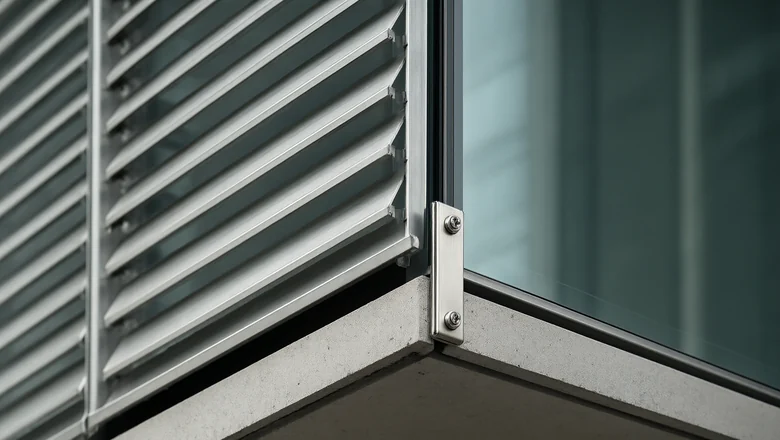
Depth is a compromise between thermal buffer, cleaning access and the amount of facade you can afford to lose. A deep cavity works as a buffer and lets a person reach the glass edge; it also costs money, increases the wind-exposed bracket cantilever and, in a Gulf summer, turns into a hot box. The numbers below are the bands we design to for a 4.0 m module.
| Cavity depth | Cleaning and inspection | Glass replacement | Thermal buffer | Typical use |
|---|---|---|---|---|
| 80–120 mm | Blade row removal only | Screen removed locally | +1–3 K | Low-rise feature walls, tight sites |
| 150–250 mm | Brush or rope from BMU | One blade row out | +2–5 K | Standard commercial towers |
| 300–450 mm | Hand access for inspection | Suction lifter from outside | +4–8 K | High-rise, 4.0 m modules |
| 500–600 mm | Walk-in inspection bay | Full unit extraction | +6–10 K | Landmarks, double-skin |
For most towers we specify 200–300 mm. It is enough to get a brush and a hand to the glass edge, it keeps the bracket cantilever modest, and it still produces a measurable buffer. The cavity must be ventilated, not sealed: openings of 1–2% of the screen area at the head and at the sill let the hot air escape. In a 45 °C Gulf design the cavity air can sit at 60–70 °C in still conditions, and the IGU edge seal — not the glass — is the temperature-sensitive component. Venting the head is what keeps the seal inside its range.
Drainage follows the same logic as a rainscreen: the outer screen takes the momentum out of the rain, the cavity drains at every floor, and the IGU wall remains the waterproof line. Put a continuous drained sill at the base of each module, a 10 mm weep path, and a removable filter at the low point. Never rely on the screen as the water barrier, and never seal the cavity bottom — a sealed cavity in a dusty climate becomes a mud tray.
How do you keep the two load paths separate?
The single most common hybrid failure is a screen bracket fixed to a unitised mullion. It looks efficient and it is wrong. The mullion is designed for wind pressure on a 1.5 m module, not for a 4.0 m screen cantilever, and tying the two together feeds inter-storey drift into the glass frame. The screen must be carried by its own brackets off the slab edge or the primary structure, with slotted holes that let the structure move while the screen stays in plane.
| Item | Design value | Why |
|---|---|---|
| Structure / slab edge | ±20 mm | As-built tolerance to be surveyed before fabrication |
| Screen bracket adjustment | ±15 mm, three axes | Absorbs survey and embed error without packing plates |
| Bracket spacing | 1.5–2.4 m | Keeps blade rail deflection within L/300 |
| Setting-out | ±3 mm | Blade line must read straight at 4.0 m module height |
| Inter-storey drift | ±7.2 mm (H/500 at 3.6 m) | Slotted bracket, ±10 mm travel |
| Thermal movement | 4.6 mm at 4.0 m, ΔT 50 K | α = 23 µm/m·K for 6063-T5 |
| Blade tip to glass | ≥ 25 mm | 10 assembly + 4.6 thermal + 7.2 drift + 3 setting-out |
The 25 mm clearance is not a round number; it is the sum of four independent movements. If the blade is allowed to sweep within 10 mm of the glass, a combination of drift and a hot afternoon will touch the IGU, and the first symptom is a scratched Low-E coating that nobody can repair in place.
Wind is the other half of the load path. A permeable outer screen does reduce the pressure coefficient on the glass behind it — measurements typically show 0.2–0.4 of Cp reduction — but we do not take design credit for it unless the project has a wind-tunnel test of the actual hybrid geometry. The unitised wall is engineered to 4.5 kPa to ASTM E330 with no credit, and the screen is engineered to 45 m/s service wind with 150+ FEA load cases. Treating the screen as a free windbreak is how a hybrid ends up under-designed.
How much solar gain and cooling energy does the screen actually save?
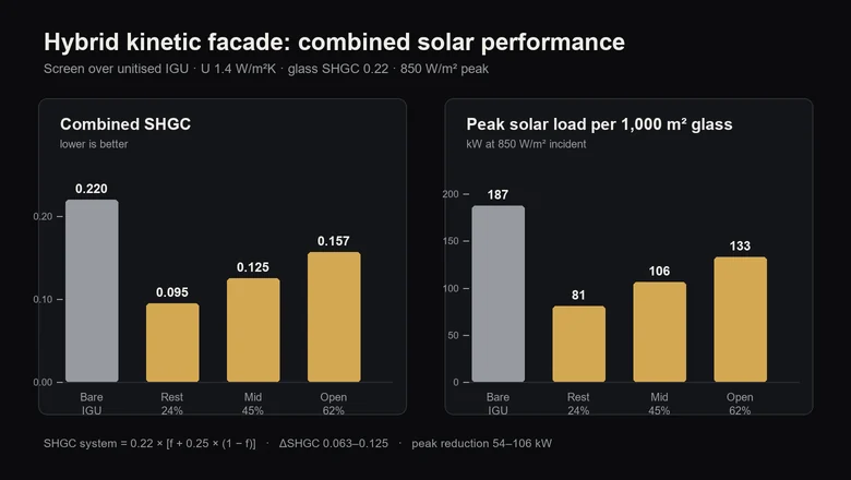
There is no need to guess. The combined SHGC of a screen plus glass can be estimated from the open fraction and one assumption about how much intercepted radiation returns to the glass as diffuse reflection. We use a quarter, which is conservative for bright anodised blades.
SHGCsystem = SHGCglass × [fopen + 0.25 × (1 − fopen)]
| Screen state | Free area | Combined SHGC | Peak solar load per 1,000 m² glass* | Reduction |
|---|---|---|---|---|
| No screen (bare IGU) | — | 0.22 | 187 kW | — |
| At rest | 24% | 0.095 | 81 kW | 57% |
| Mid-open (about 45°) | 45% | 0.125 | 106 kW | 43% |
| Fully open (90°) | 62% | 0.157 | 133 kW | 29% |
*At 850 W/m² incident on the glass plane, which is a realistic west-facing peak for the Gulf and East Africa.
Convert that into annual energy and the result is respectable but not transformative. At 900 peak-equivalent hours, 1,000 m² of screened west glass saves about 95 MWh of cooling energy against the bare wall, which is roughly 30 MWh of electricity at a chiller COP of 3.2 — about USD 3,000 a year at USD 0.10/kWh. The screen does not pay for itself on energy alone. It pays for itself through comfort, glare control, a smaller chiller plant and the facade image; the energy is the dividend, not the business case.
What happens to acoustics, fire and water management?
Three performance lines pass through the interface, and all three must be assigned explicitly.
- Acoustics. The sealed IGU keeps STC 42 only if it stays sealed. A 24% open screen in front of it does not raise the rating; on its own it can reduce it at low frequency. With a 50 mm absorptive liner on the cavity side, tests and practice show 3–6 dB of additional attenuation in the 500–2,000 Hz band, with essentially no benefit below 125 Hz. Specify the acoustic performance of the IGU, and treat the screen as a mid-frequency bonus.
- Fire. The rated line remains the unitised wall plus the perimeter firestop — EI 60 or EI 120 to EN 13501-2, with the slab-edge barrier continuous behind the screen. Blades should be A2-s1,d0 to EN 13501-1, and where the cavity exceeds 300 mm, cavity barriers are needed at each floor so the gap cannot act as a chimney. The screen is outside the compartment; it must never be the reason a firestop is interrupted.
- Water. The screen intercepts an estimated 40–60% of wind-driven rain at the rest position, which is useful but not a waterproofing strategy. The IGU wall keeps its 750 Pa ASTM E331 test and EN 12154 RE 1200 classification, and the cavity drains at every floor. Test the wall with the screen installed, because a screen can hide a leaking joint during the site test and reveal it two winters later.
How do you detail the hybrid for 45 °C Gulf and tropical East Africa?
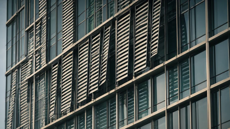
The two target regions fail in different ways. The Gulf is a heat, dust and chloride problem; East Africa is a rain, humidity and biological-growth problem. The same hybrid detailing cannot be copied between them without changes.
| Parameter | Gulf: 45 °C, ISO 9223 C4–C5 | East Africa: highlands and coast |
|---|---|---|
| Design ambient | 45 °C; dark blade surface 75–80 °C | 26–34 °C; coastal humidity 70–90% |
| Design wind | 45 m/s service, 150+ FEA cases | About 26.9 m/s, project-verified |
| Cavity strategy | Ventilated and drained; head vents essential | Ventilated with insect mesh; mould-resistant coatings |
| Finish | AA25, 5–20 µm, 200–500 HV, ΔE ≤ 2.5 | AA25 or PVDF; A4 stainless in coastal C4–C5 |
| Dust and cleaning | Blade-root accumulation; clean every 6 months | Pollen and spores; clean every 12 months, inspect drains after long rain |
| Rain regime | 50–100 mm/h short intense storms | 10–30 mm/h long events, 800–1,500 mm/year |
In the Gulf the enemy is the sealed hot box. A cavity without head vents will sit above 70 °C, cook the IGU edge seal and expand the blades into their clearance. In East Africa the enemy is standing water: a cavity that drains poorly grows algae on the blade roots and stains the glass, and the long rain events find every unsealed penetration. Both are solved by the same discipline — ventilate the head, drain the sill, and keep the bracket penetration sealed on the warm side of the insulation.
Who owns the interface, and how is it commissioned?
A hybrid package fails commercially far more often than it fails technically, because the interface sits between two scopes. The matrix below is the one we write into the tender.
| Interface item | Owner | Acceptance record |
|---|---|---|
| Slab-edge embed and pull-out test | Structure | 1.5× test load, 10% sampling |
| Bracket design and supply | Kinetic supplier | Calculation + FEA, 150+ cases |
| Penetration through insulation and membrane | Envelope contractor | Sealed and photographed before cover |
| Setting-out datum and module line | Envelope contractor | ±3 mm survey, signed |
| Blade alignment and activation | Kinetic supplier | Clearance sweep, activation at 0.9 m/s |
| Air and water test of the wall | Envelope contractor | 750 Pa with screen installed, witnessed |
| Firestop continuity | Envelope contractor | 100% compartment photographs, index |
The mock-up must include the interface, not just the wall. We ask for two bays wide by two storeys high with a 1.5 m return, which is 0.5–1.5% of a typical package and 12–20 weeks including procurement. On that mock-up the sequence is: air and water test with the screen fitted, blade clearance sweep through the full stroke with the structure at both drift extremes, activation test at 0.9 m/s, torque check on 10% of brackets, and a drain-down test with water at the sill. If the screen is installed after the wall test, the test proves nothing about the finished facade.
What should the specification clause say?
- Hybrid configuration stated by area: screened percentage, screened bays, and the transition detail at every boundary.
- Unitised wall performance without wind credit: 4.5 kPa structural, 750 Pa water, A4/RE 1200, U ≈ 1.4, SHGC ≤ 0.22, STC 42.
- Screen performance: 6063-T5, AA25 5–20 µm, 200–500 HV, 24%/62% free area, activation below 0.9 m/s, service wind 45 m/s.
- Cavity: depth, top and bottom ventilation area, drained sill, removable filter, inspection access.
- Clearances: blade tip to glass ≥ 25 mm at full stroke with drift and thermal movement combined.
- Load path: screen brackets independent of mullions, slotted for ±10 mm, A4 stainless, isolation washers.
- Fire: A2-s1,d0 blades, EI 60/120 perimeter barrier continuous behind the screen, cavity barriers at each floor where depth > 300 mm.
- Testing: air and water with the screen installed; mock-up 2 bays × 2 storeys + 1.5 m return; 1.5× anchor pull-out.
Key takeaways
- The glass line stays sealed and rated; the screen only owns shading and image. Do not merge the two performance responsibilities.
- A 200–300 mm cavity is the commercial default: cleanable, drainable, and still a useful thermal buffer.
- Combined SHGC falls from 0.22 to 0.095–0.157, cutting peak solar load by 29–57% on 1,000 m² of west glass.
- Energy alone does not pay for the screen; comfort, glare and plant reduction complete the case.
- Never fix the screen to a unitised mullion, and keep 25 mm between blade tip and glass at full stroke.
- Test air and water with the screen installed, or the test says nothing about the building you hand over.
Frequently asked questions
Can kinetic louvres be fitted over a unitised curtain wall?
Yes. The usual arrangement is an independent screen on its own brackets, set 200–600 mm outside a complete unitised wall. The wall keeps its air, water and acoustic performance, and the screen adds adjustable shading. The two systems must not share brackets, because the glass frame is not designed for the screen’s cantilever or for inter-storey drift.
How far should a kinetic screen sit from the glass?
Two hundred to three hundred millimetres suits most towers. That depth allows brush cleaning and hand access to the glass edge, keeps the bracket cantilever modest and provides a 2–5 K thermal buffer. Use 80–120 mm only for low-rise feature walls where the screen can be removed for cleaning, and 500–600 mm only where a walk-in inspection bay is planned.
Does the outer screen reduce wind load on the glazing?
It does reduce the pressure coefficient, typically by 0.2–0.4, but we do not take design credit without a wind-tunnel test of the actual geometry. The unitised wall is engineered to 4.5 kPa with no credit and the screen to 45 m/s service wind. Treating a permeable screen as a free windbreak is a common and expensive under-design.
Who is responsible for the interface between screen and wall?
Assign it item by item in the tender: structure owns the embed and pull-out test, the kinetic supplier owns the bracket and blade alignment, the envelope contractor owns the penetration seal, the setting-out datum and the firestop. The air and water test must be done with the screen installed and witnessed by both parties.
Does adding a kinetic screen improve acoustic performance?
Not by itself. The sealed IGU provides STC 42, and a 24% open screen can reduce low-frequency performance if it is the only change. With a 50 mm absorptive liner on the cavity side, expect 3–6 dB of extra attenuation between 500 and 2,000 Hz, and nothing below 125 Hz. Specify glass for acoustics and the screen for shading.
Planning a hybrid kinetic envelope?
Send the elevation, the screened percentage and the local wind, rain and temperature data. We will return a configuration recommendation, a cavity and clearance schedule, and a combined SHGC calculation for your glass build-up.