Short answer: Unitised glazing stays maintainable only if replacement was designed in from day one. INDECO modules measure 1.5 × 4.0 m and weigh 265–410 kg, and each lifts out from outside in two to four hours on the building maintenance unit. Roof track geometry, cradle payload, tie-back anchors and wind limits are therefore design decisions, not post-handover notes.
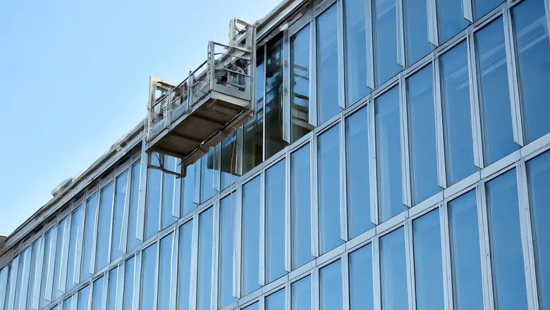
Every unitised facade eventually needs a unit replaced — a broken lite, a failed seal, a panel damaged by impact or by a storm. What decides whether that is a two-hour lift or a six-week scaffold contract is settled long before handover, in the way the roof track is laid out, the way the cradle is sized, and the way the module is detailed to release from its neighbours. This article sets out how to design unitised glazing for access and replacement, using the performance envelope we engineer to: modules up to 1.5 × 4.0 m, insulated glass from 6+12A+6 to 8+16A+12, system U-value ≈ 1.4 W/m²·K, SHGC ≤ 0.22, water tightness 750 Pa (ASTM E331) and structural wind load up to 4.5 kPa (ASTM E330).
Key takeaways
- Access is a design deliverable, not an operations note. Roof track, cradle payload and anchor loads are fixed by drawings, and cannot be retrofitted cheaply.
- Unit mass sets the machine. A 6+12A+6 module weighs 265–295 kg; an 8+16A+12 acoustic build-up weighs 370–410 kg. The BMU and its lifting beam are sized to the heaviest unit on the elevation, not the average.
- Wind governs the calendar. Cradle work normally stops at about 12.5 m/s and unit lifting at 8–10 m/s, while the facade itself is designed for 45 m/s or 4.5 kPa.
- Every unit must come out alone. If removing one module requires disturbing its neighbours, the facade is not truly unitised.
- Inspect the access system as often as the facade. Anchors and cradles are load-bearing life-safety equipment with a 12-month examination cycle.
What Is BMU Access, and Why Does Unitised Glazing Depend on It?
A building maintenance unit (BMU) is the permanent or semi-permanent machine that carries people and materials up and down a facade after the construction hoist is gone. On a unitised curtain wall, the BMU is not a cleaning convenience — it is the crane that will lift failed modules out of the wall for the next 25 to 30 years.
The dependency is structural, not cosmetic. Unitised modules interlock: the male and female stack joint of one unit engages the units above and below, and the vertical mullions of adjacent units form the drainage and pressure-equalisation cavity described in our drainage and pressure equalisation guide. A module is therefore held by geometry as much as by brackets. Releasing it means lifting it vertically clear of the stack engagement, then pulling it outward past the slabs — a movement that only makes sense from outside the building.
That is why the BMU question belongs in concept design. The roof needs a track route with enough coverage to reach every square metre of facade including returns and re-entrant corners; the structure needs to carry the track; and the parapet needs a geometry the cradle can pass over. A tower designed with a 1.8 m setback at level 20, or a crown that blocks the last three floors, will leave a zone that no cradle can reach — and that zone will be repaired by rope access or scaffold for the life of the building.
How Is a Unitised Module Actually Replaced?
The sequence is short, but every step has a load or a tolerance attached to it. On our installation sequence, modules arrive on a monorail or tower crane and are set from the slab; replacement runs that sequence in reverse, from outside, with the BMU doing the lifting.
| Step | Work | Typical duration | Load / control point |
|---|---|---|---|
| 1 | BMU positioned, cradle locked, wind checked | 30–45 min | Wind ≤ 8–10 m/s for lifting |
| 2 | Remove external pressure plate / cover cap | 20–30 min | Fasteners retained, torque logged |
| 3 | Release stack-joint interlock, free drainage cavity | 20–30 min | No load on adjacent units |
| 4 | Attach lifting beam, take the weight, lift clear | 30–45 min | 265–410 kg on BMU hook |
| 5 | Lower to roof or transfer floor, move aside | 30–45 min | Roof storage position pre-planned |
| 6 | Lift replacement unit, set, level, re-engage | 45–60 min | Bracket adjustment ±15 mm |
| 7 | Restore seals, drainage path, visual check | 30–45 min | Water test on request |
| — | Total, one module | 2.5–4 h | Excluding BMU mobilisation |
Two details decide whether that schedule holds. First, the replacement unit must be identical: the same extrusion set, the same glass build-up, the same anodising batch strategy. Because anodised finishes are matched within a batch to ΔE ≤ 2.5, a replacement made years later from a new batch will read slightly differently against its neighbours — which is why projects keep spare units from the original production run rather than ordering later. Second, the lifting interface must already exist on the unit. Factory-fitted lifting lugs or a defined beam pocket avoid site drilling into a finished frame, which would break the 5–20 µm anodic film and the corrosion protection it provides.
What Are the Main BMU Types, and Which Suits Your Tower?
Five access families cover almost every commercial tower. The right choice follows the geometry — roof plan, height, setbacks and how much of the facade is genuinely vertical.
| Type | How it reaches the facade | Typical payload | Best for | Cost index |
|---|---|---|---|---|
| Roof monorail + cradle | Fixed perimeter track, cradle descends vertically | 200–500 kg | Regular-plan towers, full unit replacement | 100 |
| Roof gantry / trolley | Bridge spans the roof, trolley traverses | 250–600 kg | Large roofs, multiple elevations, atria | 115–130 |
| Portable davit arm | Socket-mounted arms moved around the roof | 120–300 kg | Podiums, low-rise, localised elevations | 65–80 |
| MEWP / telescopic platform | Ground-based machine | 200–450 kg | Up to about 25–30 m, open sites | 50–60 |
| Rope access | Technicians on ropes from roof anchors | Personnel + tools, ≤ 30 kg | Inspection, seal repair, cleaning — not unit lifting | 20–30 |
For a unitised tower above roughly 30 m, the roof monorail with a cradle is the default: it carries the module mass, it holds the unit steady during the lift, and it gives two technicians a stable working platform. Rope access is excellent for inspection and seal work but cannot lift a 410 kg unit, so a rope-only strategy quietly converts every future glass break into a scaffold project. Machines are selected against EN 1808 for suspended access equipment and EN 13155 for the lifting attachments.
How Much Load Does the Roof Track and Structure Carry?
The BMU is a machine that hangs its whole working load off the building, so the roof structure is part of the access system. Sizing starts from the heaviest unit, not the typical one.
| Build-up | Glass | Module mass | Recommended BMU rating | Handling |
|---|---|---|---|---|
| Standard vision | 6 + 12A + 6 | 265–295 kg | ≥ 350 kg | Single hook + spreader beam |
| High-performance / acoustic | 8 + 16A + 12 | 370–410 kg | ≥ 500 kg | Two-point lifting beam, slower slew |
| Spandrel with insulation | Opaque panel | 180–240 kg | ≥ 300 kg | Single hook |
On top of the module mass, the roof must carry the cradle itself, two technicians, tools and the dynamic effect of a load that starts and stops. The practical rules used on our projects are:
- Structural safety factor. BMU supporting structure and track fixings are designed to at least 2 × the maximum working load, in line with suspended-access equipment practice.
- Lifting attachments. Non-fixed lifting devices are specified to EN 13155, with a 4:1 to 5:1 factor on the ultimate load.
- Roof live load. Maintenance walkways are designed for at least 5 kPa crowd loading plus the BMU wheel or bogie loads at each support.
- Track cantilever. Keep the free cantilever of a monorail to roughly 1.5–3.0 m; anything longer needs a specific structural check and usually a tie-back.
- Storage. Reserve 2–3 module parking positions on the roof or a transfer floor, clear of the track route, for units awaiting lift or disposal.
What Wind Speed Stops BMU Work, and What Does It Cost the Programme?
The facade is designed for far higher wind than the machine is allowed to work in. Our kinetic and glazing systems are proven for service wind up to 45 m/s and a design pressure of 4.5 kPa, but a cradle with people in it is governed by a completely different limit: stability, not strength.
| Activity | Wind limit | Rationale |
|---|---|---|
| Cradle in operation with personnel | ≤ 12.5 m/s (≈ 45 km/h, Beaufort 6) | Standard suspended-platform operating limit; cradle starts to swing and to strike the facade |
| Cradle parked and locked | ≤ 20–25 m/s | Stowed condition, restraints engaged |
| Lifting a unitised module | ≤ 8–10 m/s | A 265–410 kg panel is a sail; above this the swing cannot be controlled by tag lines |
| Rope access | ≤ 10 m/s | Technician stability and abrasion control |
Those limits convert into lost days, and the number differs sharply by region. On an inland East African site where daily gusts rarely exceed 8–10 m/s, a BMU may be available 260–290 days a year. On an exposed Gulf waterfront, the combination of shamal episodes and peak temperatures cuts usable lifting windows to roughly 200–240 days, and the 12:00–15:00 band is often lost entirely in summer. At a 45°C ambient, dark roof surfaces and the track itself reach 70–80°C, so motors, brakes and hydraulic units must be specified with derating and the work plan has to allow for shortened shifts.
The practical consequence: budget access time, not just access equipment. A maintenance plan that assumes 300 working days a year will be wrong on a coastal tower, and the shortfall shows up as deferred glass replacements — which is a safety and water-tightness risk, not just an aesthetic one.
How Do You Detail Anchors, Tie-Backs and Restraint?
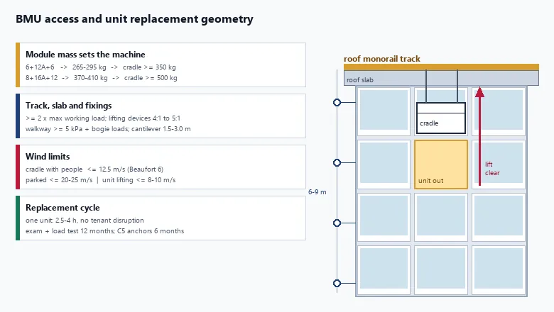
A cradle hanging 100 m up a wall is a pendulum unless it is restrained. The restraint system is a set of separate decisions, each with a standard behind it.
| Element | Requirement | Reference |
|---|---|---|
| Personal fall-arrest anchor | ≥ 12 kN static for one user; higher where two users attach | EN 795 |
| BMU track / davit base fixing | ≥ 2 × maximum working load; typical design point load 20–40 kN | Suspended-access equipment practice, EN 1808 |
| Tie-back (restraint) spacing | One restraint point every 6–9 m of descent | Cradle stability, project-specific wind study |
| Wire-rope terminations | Correctly formed and proof-loaded terminations, logged | EN 13411 |
| Roof walkway live load | ≥ 5 kPa crowd load plus bogie wheel loads | EN 1991-1-1 |
| Corrosion class | ISO 9223 C4 for coastal, C5 for splash/surf zones; A4 stainless or isolated fixings | ISO 9223 |
Tie-backs are the detail most often value-engineered away and most often regretted. Without restraint, a cradle at 60 m will swing enough to chip glass edges and to make a controlled module lift impossible. The tie-back sockets also have to be reachable: a restraint point that a technician cannot clip into from the cradle is a restraint point that will not be used.
Corrosion deserves a specific word for Gulf and coastal East African projects. Anchor plates, sockets and track fixings sit in the same chloride environment as the facade itself, and in ISO 9223 C5 exposure a carbon-steel anchor embedded in a parapet becomes the weak link in a life-safety system. Specify A4 stainless or hot-dip galvanised components with isolation from aluminium, and keep the anodised aluminium elements within the 5–20 µm film range (AA15–AA25 classes) that our anodised finish guide sets out.
Inboard or Outboard Replacement — Which Is Right for Your Building?
There are two philosophies, and the choice should be written into the specification because it changes the frame design.
- Outboard replacement. The module comes out to the outside, past the slab edge, on the BMU. This is the standard for unitised systems, needs no interior access, and keeps the building occupied during the work. It requires full BMU coverage and a roof track.
- Inboard replacement. The module comes into the floor plate — used where there is no BMU, where the facade is inside an atrium, or where the unit is a spandrel behind a grille. It needs a removable interior trim, a clear lift path inside the building, and it disrupts the tenant.
On a typical commercial tower the answer is outboard, with a small number of inboard-only zones designed explicitly: atrium walls, units behind deep reveals, and anything under a soffit the cradle cannot pass. Those zones are listed in the access drawings at tender stage, with a stated alternative method for each — usually a portable davit or a MEWP. Discovering an inboard-only zone after handover is how a two-hour job becomes a two-week one.
How Often Must the BMU and Its Anchors Be Inspected?
Access equipment is load-bearing life-safety plant. Its inspection cycle is separate from the facade inspection cycle, and on coastal projects it is shorter.
| Item | C3 inland | C4 coastal | C5 splash / surf |
|---|---|---|---|
| BMU thorough examination + load test | 12 months | 12 months | 12 months |
| Anchor / tie-back visual check | 12 months | 12 months | 6 months |
| Track fixings — torque re-check | 12 months | 6–12 months | 6 months |
| Wire ropes and terminations | 12 months | 12 months | 6–12 months |
| Anodised surfaces — wash and inspect | 12–24 months | 12 months | 6–9 months |
The 12-month thorough examination of suspended access equipment is a regulatory expectation in most jurisdictions and is written into EN 1808 practice. Anchor pull-testing is usually done on a sample basis — a proportion of anchors tested each year so that the whole population is covered over a cycle — with any anchor that shows cracking, corrosion or movement replaced rather than repaired.
What Should the Replacement and Maintenance Specification Say?
Eight clauses turn access from an intention into something that survives handover:
- Independent demountability. Every unit can be removed without disturbing the units above, below or beside it.
- Module identification. Each unit carries a permanent ID matching the elevation drawing, the QC file described in our factory quality control guide, and the glass build-up record.
- 100% BMU coverage. The access drawing demonstrates coverage of every square metre, including returns, soffits and parapet interiors, and lists any inboard-only zones.
- Factory-fitted lifting interface. Lugs or beam pockets installed in the plant; no site drilling into finished frames.
- Heaviest-unit sizing. Cradle and lifting beam rated for the heaviest module on the elevation with the stated safety factor.
- Spare units. Spare modules from the original production batch, typically 0.5–1% of facade area, stored with glass protected from UV and from thermal shock.
- High-temperature operation. Motors, brakes and controls rated or derated for 45°C ambient, with a documented hot-season work plan.
- Handover package. Anchor load calculations, examination certificates, the BMU-compatible facade declaration and the replacement method statement for each unit type.
For Saudi projects these clauses sit alongside SBC 901 and Mostadam documentation; for coastal East African and Gulf sites they are read together with the ISO 9223 exposure class used to select fixings and finishes. The facade and the machine that maintains it should be specified in the same package, by the same team, at the same time.
Design checklist for a replaceable unitised facade
- Track route drawn and structurally checked before the roof slab is poured.
- Cradle rated to the heaviest unit (410 kg for 8+16A+12), not the lightest.
- Tie-back points at 6–9 m, reachable from the cradle, in A4 stainless for C4/C5.
- Lifting lugs fitted in the factory; no site drilling into anodised frames.
- Spare units from the original anodising batch; replacement ΔE ≤ 2.5.
- Wind limits stated: 12.5 m/s for cradle work, 8–10 m/s for lifting.
- 12-month thorough examination and anchor sample testing budgeted from year one.
Frequently Asked Questions
What size BMU do I need for unitised glazing?
Size it to the heaviest module, not the average. A 1.5 × 4.0 m unit with 6+12A+6 glass weighs 265–295 kg, so the cradle needs at least a 350 kg rating; the acoustic 8+16A+12 build-up weighs 370–410 kg and needs 500 kg plus a two-point lifting beam. Add technicians, tools and the cradle itself, then design the track and its fixings to twice the maximum working load.
Can a unitised module be replaced from inside the building?
Sometimes, but it is the exception. Inboard replacement is used in atria, behind grilles, or where no BMU can reach, and it needs a removable interior trim and a clear lift path through occupied space. On a normal commercial tower the unit comes out to the outside on the BMU in 2.5 to 4 hours with no tenant disruption. Any zone that must be replaced inboard should be listed at tender.
How many spare units should a project keep?
A practical reserve is 0.5 to 1% of facade area, taken from the original production run. Spares matter for colour as much as for glass: anodised finishes are matched within a batch to a colour difference of 2.5 or less, so a module made years later from a new batch will not match. Store spares flat, with glass protected from UV and from thermal shock.
What wind speed stops facade maintenance work?
A cradle carrying people normally stops at about 12.5 m/s, roughly 45 km/h or Beaufort 6, and is parked and locked above 20 to 25 m/s. Lifting a module is stricter still: 8 to 10 m/s, because a 265 to 410 kg panel behaves like a sail. Note that the facade itself is designed for far more — 45 m/s service wind or 4.5 kPa — so the access limit, not the wall, sets the calendar.
How often do BMU anchors need testing?
The machine itself needs a thorough examination with load test at least every 12 months, and anchors are visually inspected on the same cycle — every six months in ISO 9223 C5 splash or surf exposure. Pull-testing is usually done on a rotating sample so the full anchor population is covered across a few years. Any anchor showing cracking, corrosion or movement is replaced, not repaired.
Planning the access strategy for a unitised tower?
Send us the roof plan, elevation and module schedule. We return an access and replacement package: track coverage drawing, cradle and anchor load calculations, unit mass schedule, spare-unit strategy and the replacement method statement — aligned to SBC 901 / Mostadam documentation for Saudi projects. See the Unitised Glazing product page, the installation sequence guide, the unitised curtain wall guide and the performance testing guide, or talk to our engineering team.