
A moving facade is a machine hung on a building, and installation is the process that either makes or breaks that machine. Fix the brackets out of line and the blades bind. Skip the sweep test and you hand over a screen that looks finished but never moves. Get the sequence right and the same elevation that shaded itself in the factory yard keeps shading itself for 25 years, in a 45 m/s gust, with no actuator to commission. Kinetic architecture — dynamic or responsive architecture — is defined by envelope parts that move without loss of structural integrity; the site work is what turns that definition into a calibrated assembly.
This article sets out how the blade family in our kinetic louver facade range actually goes up: what a module weighs, the tolerance chain from slab edge to blade tip, what the brackets carry at 45 m/s, an eight-step sequence, realistic crew output, and the checks that prove the mechanism was installed free. It complements the movement-type comparison and the test regimes that the same modules are qualified against.
What makes kinetic facade installation different from a fixed screen?
Three things, and all three are about movement. First, the assembly owns clearances that a fixed screen does not: adjacent blades must never touch through the full 0–90° sweep, so the module is set with a minimum 10 mm blade gap at every position, not just at rest. Second, pivots at each end of a blade have to stay coaxial; a bracket twisted by 2–3 mm over a 4.0 m span adds friction torque that a passive blade driven by wind pressure below 0.9 m/s simply cannot overcome. Third, completion is not visual — it is functional. Every blade is swept and logged before handover, because a static blade is a fixed louvre sold at a kinetic price.
The environment adds a fourth difference. A kinetic screen has two design wind states, not one: activation at 0.9 m/s (about 2 mph) and a 45 m/s service wind, which is 1,241 Pa of dynamic pressure at q = 0.613V². Installation has to land inside both. Modules go up in breezes light enough to handle a 4.0 m unit safely — lifting stops at about 10 m/s — while the permanent fixings are designed for roughly 2,500 times that pressure at the corners.
How are kinetic facade modules built and delivered?
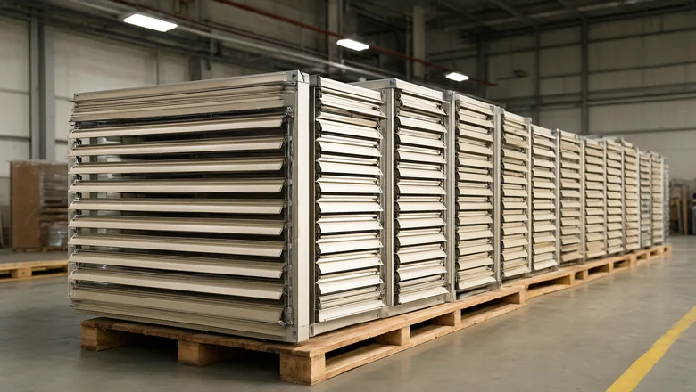
A module is a 4.0 m wide frame carrying one storey of blades: extruded 6063-T5 blades on stainless pivot bearings at each end, balanced by a return spring, all pre-set in the factory so that site work is setting, levelling and locking rather than assembly. Blades come in 100, 150 and 200 mm chords on 130, 190 and 250 mm pitch. One useful consequence for lifting: chord choice barely changes weight, because a wider blade is also a rarer one.
| Blade chord / pitch | Blades per m² | Blade mass per m | Blade mass per m² | Module mass (4.0 × 4.0 m) | Open area at rest |
|---|---|---|---|---|---|
| 100 mm / 130 mm | 8.0 | 1.35 kg/m | 10.8 kg/m² | 220–250 kg | 26% |
| 150 mm / 190 mm | 5.3 | 1.95 kg/m | 10.3 kg/m² | 210–240 kg | 24% |
| 200 mm / 250 mm | 4.0 | 2.60 kg/m | 10.4 kg/m² | 215–245 kg | 23% |
At 13–16 kg/m² a kinetic module is roughly a third of the mass of a unitised glazed unit of similar area, which is why the lifting plant on a kinetic package is usually sized by reach and cycle time rather than by capacity. Factory framing also means the module arrives with its blade geometry already verified: the same 23–26% open area at rest that the daylight calculations assumed.
Delivery and storage follow three rules. Modules travel on A-frame racks, 24–32 per 40 ft high-cube for a single-storey module, or as frame kits plus blade bundles when storey height exceeds the container door aperture — knocked-down shipping roughly doubles the square metres per box but moves the labour to site. On site, modules are stored flat on dunnage, covered but ventilated, with a buffer of two to three floors ahead of the fixing crew. Protective film comes off within 60–90 days of delivery; left longer in 45 °C sun it bonds to the anodised layer and takes the gloss with it.
What tolerance chain must the installation absorb?
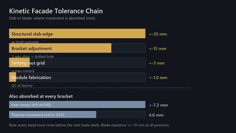
Every facade package is a chain of tolerances; the kinetic one has an extra link, because the last link is a bearing that has to stay free. The chain closes from the structure inward: what the concrete gives you, what the bracket absorbs, what the survey controls, and what the factory guarantees.
| Link | Tolerance | Who owns it | Consequence if exceeded |
|---|---|---|---|
| Structural slab edge | ±20 mm | Main contractor | Bracket shim stack runs out; resort to packing plates |
| Bracket adjustment (3-way) | ±15 mm | Facade contractor | Modules forced out of plane; joints step |
| Setting-out grid | ±3 mm | Facade surveyor | Accumulating drift up the elevation |
| Module fabrication | ±1.0 mm (diagonal ≤1.5 mm) | Fabricator | Pivot misalignment, binding blades |
| Blade clearance in sweep | ≥10 mm at all angles | Installer | Blades touch, noise, wear, stalled motion |
| Inter-storey drift (H/500) | ±7.2 mm | Structural engineer | Bracket slot must accommodate without jamming |
| Thermal movement (4.0 m, ΔT 50 K, α = 23 µm/m·K) | 4.6 mm | Designer | Frame elongation; pivots load axially |
The practical rule is that each band has to be closed and signed before the next trade starts. Survey the slab, record deviations, set brackets to the corrected grid, then set modules. Where the structure is worse than ±20 mm — common on fast-track frames in both Gulf and East African markets — the answer is a deeper adjustment bracket or a cast-in channel, not grinding the module.
How are modules anchored, and what does the bracket carry?
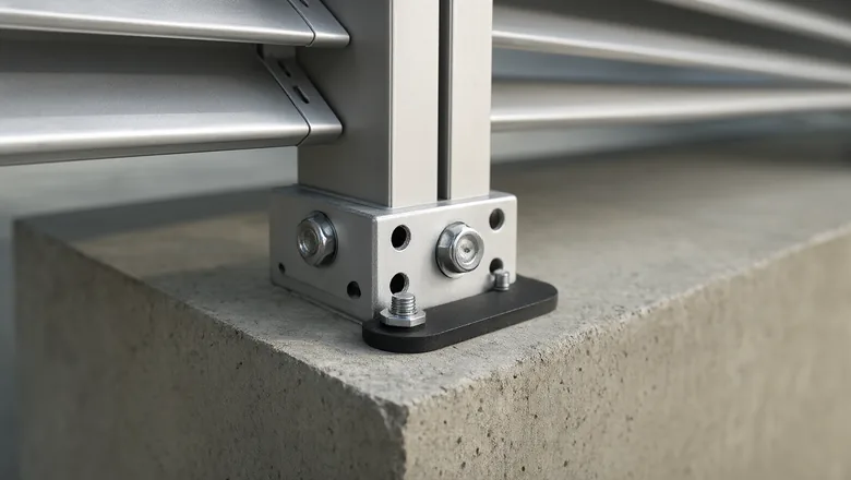
The bracket is the whole structural story in one component. It carries the module dead load, the wind pressure and suction on the blades, and it holds the pivot alignment that the mechanism depends on. On a Gulf reference designed for 45 m/s, that means corner pressures around 2.1–2.5 kPa once local amplification of 1.7–2.0× is applied to the 1,241 Pa reference dynamic pressure — which is why the anchorage, not the blade, is usually what governs the fixing design.
| Check | Typical requirement | Why |
|---|---|---|
| Reference dynamic pressure | 1,241 Pa at 45 m/s (q = 0.613V²) | Sets every downstream load |
| Corner / edge pressure | 2.1–2.5 kPa / 1.6–2.0 kPa | Amplification 1.7–2.0× and 1.3–1.6× |
| Screen design pressure | 4.5 kPa, verified to 6.75 kPa (1.5×) | Proof margin on the anchor and bracket |
| Fixings per bracket | ≥4, edge distance ≥2.5 × diameter | Prevents concrete breakout under suction |
| Fastener material | A2 stainless inland, A4 in C4/C5 coastal | ISO 9223 corrosivity; chlorides at the coast |
| Galvanic isolation | EPDM or nylon pad between aluminium and steel | Stops bimetallic corrosion at the slab edge |
| Torque audit | ±10% of specified value, 10% sample | Over-torque distorts the bracket and binds pivots |
| Fire at the slab edge | A2 cavity barrier per floor (EN 13501-1) | Screen cavity must not become a flue |
Blade finish matters here too. An anodised layer of 5–20 µm at AA25, 200–500 HV, is not a paint film that a site touch-up can match; where a bracket is cut or drilled on site, the exposed edge is dressed and the fixing isolated rather than coated. The wind-load article sets out how the 150+ load cases behind these numbers are assembled.
What does the eight-step installation sequence look like?
- Survey and set out. Record the as-built slab edge every bracket position; issue a deviation drawing before any bracket is ordered or shimmed.
- Fix brackets. Cast-in channels or post-fixed anchors, three-way adjusted to the corrected grid, isolation pads in place, torque audited.
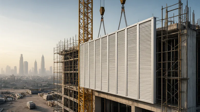
- Hoist the module. 210–250 kg on a spreader beam or two-point lift, wind limit about 10 m/s, tag lines to control swing.
- Land and level. Module hung on the bracket, plumbed to ±1.5 mm, then partially locked — never fully torqued until the bay is set.
- Close the joint. Module-to-module weather line, cavity barrier at the slab edge, drainage path kept continuous.
- Set the bay. Four to six modules adjusted together so the blade lines read straight across joints; then full torque.
- Sweep and log. Every blade moved through 0–90° by hand; bind, noise or lag recorded and rectified the same day.
- Commission and hand over. Activation check, photography of each bay, torque record, module ID register, and the maintenance schedule handed to the operator.
The sequence is deliberately bay-by-bay rather than floor-by-floor. Blades are visually unforgiving: a 2 mm step between modules is obvious at 200 m, and it is far cheaper to adjust six modules as a set than to re-hang a completed floor.
What programme and crew output should be allowed?
| Activity | Output | Crew / plant | Limits |
|---|---|---|---|
| Setting out | 60–90 bracket positions per day | 2 surveyors | Structure accessible, drawings agreed |
| Bracket installation | 40–70 brackets per day | 3 fitters | Cure time for post-fixed anchors |
| Module lifting and setting | 10–14 modules (160–220 m²) per day | 6 + crane or monorail | Lifting stops near 10 m/s |
| Factory-assembled screen, average | 22–35 m² per worker-day | — | Pre-assembled modules |
| Site-assembled (stick) screen | 8–14 m² per worker-day | — | Blade-by-blade assembly |
| Sweep test and QA logging | 25–40 modules per day | 2 technicians | Access platform available |
| Manned platform work | — | Cradle or MEWP | ≤12.5 m/s; park above 20 m/s |
Pre-assembly is worth roughly two to three times the site productivity of stick assembly, and it buys something harder to price: the pivots are set in a jig, not on a scaffold. Working against that, a kinetic package still needs access for the sweep test over the whole elevation, so the programme has to include a second pass with platforms, not just the fixing pass. Weather allowance is regional: plan on 200–240 working days a year in the Gulf and 260–290 in East Africa.
How is blade movement verified before handover?
- 100% sweep. Every blade moved through its full travel by hand or fan; any bind, graze or delay is logged against the module ID.
- Clearance check. ≥10 mm between adjacent blades and between blade and frame at every angle, verified with a gauge on a 10% sample.
- Activation check. Passive blades begin to move below 0.9 m/s; confirmed on a 10% sample with a calibrated anemometer held at the blade face.
- Pivot and spring audit. Bearing friction and spring preload within ±10% of the setting, sampled 10%, with any outlier module re-set.
- Photographic record. Each bay photographed closed and open, indexed to the module register, so the first-year inspection has a baseline.
- Documentation. Torque records, anchor pull-out tests at 1.5×, module IDs and the inspection intervals handed over with the maintenance schedule.
These are the site half of the story. The laboratory half — cycling to 182,500–365,000 strokes, water penetration in three blade positions, structural proof at 6.75 kPa — is covered in kinetic facade testing, and the drive options behind motorised variants in passive vs motorised actuation.
What changes on 45°C Gulf and East African sites?
| Factor | Gulf (45°C design) | East Africa |
|---|---|---|
| Design wind | Up to 45 m/s reference; corner 2.1–2.5 kPa | Typically 26–30 m/s; corner pressure roughly half |
| Corrosivity (ISO 9223) | C4 inland, C5 on the waterfront — A4 fasteners | C3 inland, C4 coastal; A2 usually sufficient inland |
| Surface temperature | Dark blades 75–80°C; sealant only below 40°C substrate | 60–70°C peak; wider working window |
| Dust and sand | Sealed pivots, covers during storage, more frequent wash-downs | Red dust in dry season; rinse before sweep tests |
| Working days per year | 200–240 | 260–290 |
| Code and rating context | Saudi Building Code + Mostadam | Local codes, commonly with international reference standards |
Two site habits pay for themselves in hot climates. Work the early shift so that sealant and adhesive work happens below a 40 °C substrate, and keep the protective film on until the last possible moment — but never past 90 days. Both are cheaper than a blade replacement.
Key takeaways
- Install kinetic facades as factory-assembled 4.0 m modules: 210–250 kg each, 13–16 kg/m², about a third of a glazed unit.
- Close the tolerance chain in order — ±20 mm slab, ±15 mm bracket, ±3 mm survey, ±1.0 mm module — and keep ≥10 mm blade clearance through the sweep.
- Design the bracket for the corner case: 2.1–2.5 kPa at 45 m/s, proofed at 1.5×, with A4 stainless and isolation pads in C5.
- Budget 22–35 m² per worker-day for pre-assembled screens against 8–14 m² for site assembly, plus a second pass for sweep testing.
- Handover is functional, not visual: 100% of blades swept, activation below 0.9 m/s verified, all records indexed to module IDs.
Frequently asked questions
How is a kinetic facade installed?
As factory-assembled modules. A 4.0 m frame carrying one storey of 6063-T5 blades arrives pre-pivoted, is lifted onto brackets that adjust ±15 mm in three directions, levelled with its neighbours, then locked. Every blade is swept by hand before the bay is signed off.
How heavy is a kinetic facade module?
Around 210 to 250 kg for a 4.0 by 4.0 m module, or 13 to 16 kg per square metre. Blade chord barely changes that: 100, 150 and 200 mm blades all work out at roughly 10.3 to 10.8 kg of aluminium per square metre of screen.
What tolerances does a kinetic facade installation have to absorb?
Four bands: plus or minus 20 mm of as-built slab edge, ±15 mm of three-way bracket adjustment, ±3 mm of setting-out accuracy and ±1.0 mm of module fabrication. In service the bracket also takes 7.2 mm of inter-storey drift and 4.6 mm of thermal movement.
How fast can a kinetic facade be installed?
A six-person crew with a crane or monorail sets 10 to 14 modules a day, roughly 160 to 220 square metres. That is two to three times the output of assembling blades on site, where 8 to 14 square metres per worker-day is typical.
What wind speed stops kinetic facade installation?
Module lifting stops at about 10 m/s, because a 4.0 m screen catches too much wind to place safely. Work from a manned cradle or platform continues to about 12.5 m/s, and plant is parked above 20 m/s.
How do you know a kinetic facade was installed correctly?
By function, not appearance. Every blade is swept through 0 to 90 degrees with no binding, clearances of at least 10 mm are gauged on a sample, passive blades are proven to move below 0.9 m/s, and pivot friction and spring preload are audited within 10 percent.
Planning a kinetic facade package?
Send the elevation, the wind study and the site logistics plan. We return a module layout with weights and lifting points, a tolerance and bracket schedule, a programme with crew output, and the handover checks. Start from the kinetic louver facade range, read movement types and cost drivers, or talk to our engineering team.