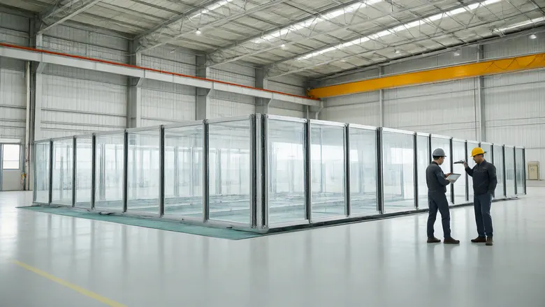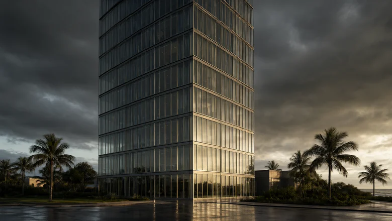
Unitised facades in hurricane and cyclone regions are not a heavier version of a temperate-climate wall. They are a different pressure problem, a different water problem and a different failure mode. A temperate tower is designed around 1.0–1.5 kPa of wind and a few hundred pascals of rain pressure; a cyclone-exposed tower in the Gulf, the East African coast or the South China Sea is designed around 3–6 kPa at the corners, with wind-driven rain arriving at 200 L/h·m² and debris travelling at 15 m/s. In an INDECO factory-assembled module of up to 1.5 × 4.0 m and 300–450 kg, the same aluminium frame that reads 4.5 kPa of structural capacity in the standard system has to be re-checked zone by zone, because the corner of the building sees roughly twice the field pressure and the corner is where the mullion is least restrained.
The engineering answer has three parts, and they are not interchangeable. The glass build-up has to stay in the frame after a break, which means a laminated inner lite with an ionoplast interlayer rather than a monolithic toughened pane. The drained and ventilated rebate has to shed 200 L/h·m² without letting water past the inner seal, which is a pressure-equalisation question rather than a gasket question. And the anchorage has to transfer uplift from a corner module into the slab without relying on the interlock as a structural member. The rest of this article works through each part with the numbers a facade engineer actually uses, and it follows the same detailing logic as our drained and ventilated rebate guide and the module specification reference.
How do unitised facades perform in hurricane and cyclone regions?
The honest one-line answer is: better than stick-built systems, because every module is a complete, factory-sealed pressure boundary that has already been cycled, sprayed and proof-loaded in a laboratory. The performance is not better because the aluminium is stronger. It is better because the water seal, the air seal and the structural connection are all completed under factory control and then verified as one assembly, instead of being made good from a cradle at 80 m in a force 10 gust.
The design pressure starts from the basic wind speed, and the relationship is quadratic. Dynamic pressure follows q = 0.613 V² with q in pascals and V in metres per second, so doubling the wind speed quadruples the load. That single equation explains why a cyclone region cannot be served by a wall designed for a temperate gust.
| Basic wind speed | Dynamic pressure q | Field zone (×1.2) | Edge zone (×2.0) | Corner zone (×2.7) |
|---|---|---|---|---|
| 45 m/s (162 km/h) | 1.24 kPa | 1.49 kPa | 2.48 kPa | 3.35 kPa |
| 50 m/s (180 km/h) | 1.53 kPa | 1.84 kPa | 3.07 kPa | 4.14 kPa |
| 55 m/s (198 km/h) | 1.85 kPa | 2.23 kPa | 3.71 kPa | 5.01 kPa |
| 60 m/s (216 km/h) | 2.21 kPa | 2.65 kPa | 4.42 kPa | 5.97 kPa |
| 65 m/s (234 km/h) | 2.59 kPa | 3.11 kPa | 5.18 kPa | 6.99 kPa |
| 70 m/s (252 km/h) | 3.00 kPa | 3.61 kPa | 6.01 kPa | 8.11 kPa |
Read the 60 m/s row against the standard product envelope and the conclusion is immediate. The standard INDECO system is rated to 4.5 kPa of structural wind load, which covers the field and the edge at 60 m/s but leaves the corner zone 33% short. That is not a defect in the wall; it is a design instruction. Every cyclone project we quote divides the elevation into field, edge and corner zones, and the corner band — typically the outer 10% of the plan dimension on each face, and never less than 1 m wide — is issued with a reinforced mullion, a reduced module width or both. A single uniform module across the whole elevation is the most common specification error we see on cyclone towers, and it is invisible until the first design-review meeting.
- Zone the elevation, do not average it. Field, edge and corner bands carry different pressures and need different mullion sections.
- Corner band definition: the lesser of 10% of the least plan dimension or the height to the first setback, and never under 1 m.
- Internal pressure matters: a nominally sealed envelope takes GCpi = ±0.18, but a wall with a failed door or an open stair can be treated as partially enclosed at ±0.55 — a 50% uplift on every module.
- Deflection limit, not stress limit, governs: the mullion usually fails L/175 or the 20 mm glazing-bed limit long before it reaches yield.
- Uplift reverses: cyclone suction pulls the module off the slab, so the anchor is designed for tension, not just shear.
Why does the glass build-up decide whether the wall stays closed?
In a cyclone the wall is breached by impact before it is breached by pressure. A 9 kg timber missile at 15 m/s carries about 1 kJ, and a monolithic toughened pane does not absorb that energy — it shatters into the full 5 mm dice and the opening is instant. Once the envelope opens, the internal pressure coefficient jumps from ±0.18 to ±0.55, and the remaining modules are loaded 50% above their design case. Most cyclone envelope failures are therefore progressive: one broken pane, then a pressure change, then a cascade of module failures on the leeward face.
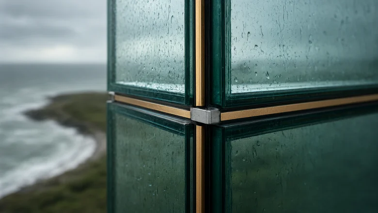
The answer is a laminated inner lite. Toughened glass provides the strength; the interlayer provides the residual. A PVB interlayer is adequate for security glazing at moderate temperature, but it softens above about 30 °C and creeps under sustained load, which is exactly the condition of a dark spandrel or a west-facing vision panel at 45 °C. An ionoplast (SGP-class) interlayer holds its shear modulus across that range, so the broken lite stays bonded, the opening does not form and the pressure coefficient never changes.
| Design pressure (corner) | Vision build-up | Inner lite | Interlayer | Deflection check |
|---|---|---|---|---|
| up to 2.5 kPa | 6 + 12A + 6 | 6 mm heat-strengthened | 0.76 mm PVB | L/175 |
| 2.5–3.5 kPa | 6 + 12A + 6.76 | 6 mm laminated, HS/HS | 0.76 mm ionoplast | L/175 |
| 3.5–4.5 kPa | 8 + 16A + 8.76 | 8 mm laminated, HS/HS | 1.52 mm ionoplast | L/175 and 20 mm |
| 4.5–6.0 kPa | 10 + 16A + 10.76 | 10 mm laminated, HS/HS | 1.52 mm ionoplast | L/240 or reduced module |
| above 6.0 kPa | 12 + 16A + 12.76 | 12 mm laminated, HS/HS | 1.52 mm ionoplast | reduced module width |
Two details complete the build-up. First, heat-soak testing to EN 14179-1 is not optional on cyclone facades: nickel sulphide inclusions in toughened glass cause spontaneous breakage months after installation, and a spontaneous break in a wall designed for impact resistance wastes the whole strategy. Second, the glazing bed and the structural bite have to be sized for the post-breakage case, because a laminated lite that stays in the frame still deflects further than an intact one — our structural glazing bite and 45 °C durability guide covers the arithmetic.
How does a drained unitised system handle wind-driven rain at 60 m/s?
It does not resist the water; it equalises the pressure so the water has no reason to cross the line. At 60 m/s the stagnation pressure on the windward face is 2.21 kPa and the rain flux is around 200 L/h·m², which is roughly a hundred times the 3.4 L/h·m² of a static ASTM E331 test. A gasket that holds 3.4 L/h·m² will not hold 200, so the design cannot be a sealing design. It has to be a drainage design with a pressure-equalised cavity behind the outer seal.
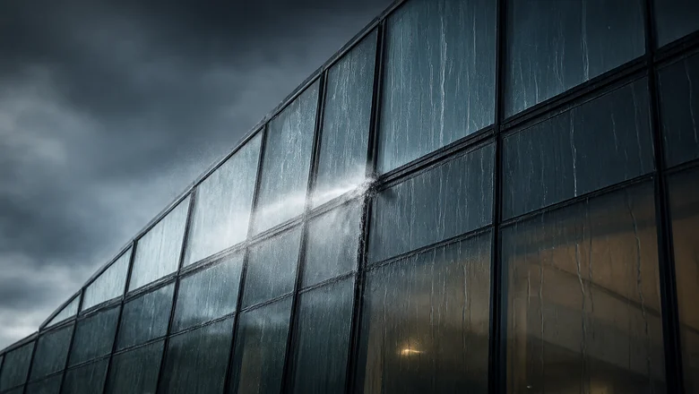
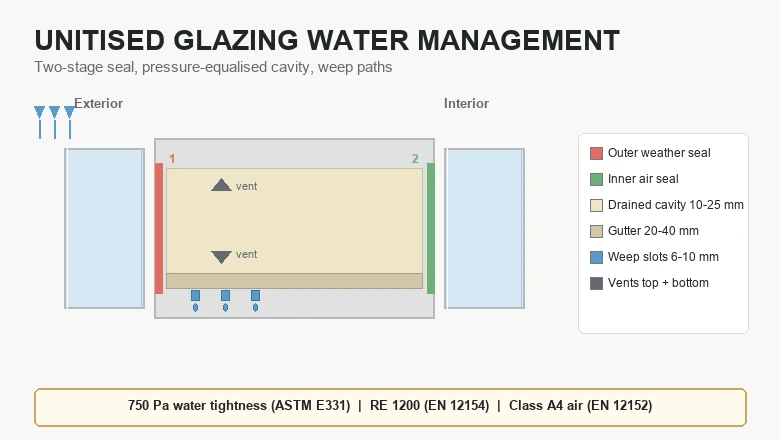
The mechanism is standard two-stage weatherproofing, but the numbers change at cyclone pressure. The outer gasket sheds most of the water, the equalisation chamber behind it vents to the face through slots sized to keep the cavity within about 200 Pa of the external pressure, and any water that does enter drains down the rebate to a weep that discharges to the face — never into the spandrel cavity, never onto the fire barrier. At 2.2 kPa the vent area has to grow, because a cavity that cannot follow the gust becomes a pump: pressure builds outside, the cavity lags, and the differential pushes water past the inner seal on the return stroke.
| Test | Pressure | Water rate | What it proves on a cyclone facade |
|---|---|---|---|
| ASTM E331 static | 750 Pa | 3.4 L/h·m² | Baseline seal integrity, no dynamic component |
| AAMA 501.1 dynamic | 240 Pa | 204 L/h·m² | Rain-screen behaviour under realistic wind-driven rain |
| EN 12154 | up to 1,200 Pa | classification RE 1200 | European watertightness class, static |
| Project cyclone protocol | 1.5 × design (up to 9 kPa) | 204 L/h·m² | Combined dynamic water and proof load at corner pressure |
The gap between the second and fourth rows is where cyclone projects are actually won. AAMA 501.1 is a 240 Pa test — a good rain-screen check, but an order of magnitude below a 60 m/s corner pressure. Cyclone specifications therefore add a project protocol: the mock-up is sprayed at 204 L/h·m² while the pressure is cycled to the corner design value, and the inner seal is inspected after every cycle. INDECO modules are tested to EN 12152 A4 for air and EN 12154 RE 1200 for water as standard; the cyclone protocol sits on top of that, not instead of it.
- Vent the cavity to the face through slots on the outer leg, never through the inner seal line.
- Weep to the face at every module base, with a minimum 8 mm drain and a 25 mm gravel guard.
- Keep the fire barrier dry: route the weep clear of the perimeter fire containment, or the barrier becomes a sponge.
- Slope the rebate: a 3° fall to the weep turns standing water in the cavity into a drained film.
- Check the interlock gasket in shear, not compression — at 2 kPa the stack joint moves and a compression-only gasket opens.
How are corners, parapets and the base detailed for cyclone uplift?
They are detailed as the three places where the load path turns, and each turn is a place where a standard detail fails quietly. The corner is where the pressure is highest and the mullion is least restrained, because the two adjacent faces give it no continuous line to distribute into. The parapet is where the wall is most exposed and least supported, since the top module sits above the last slab and cantilevers the coping into the highest suction on the building. The base is where the water arrives and where the fire barrier has to stay dry.
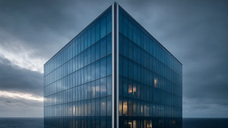
At the corner, the module is detailed with a reinforced mullion or a closed-section corner post, the anchor pitch drops from the typical 1,200 mm to 600–750 mm, and the interlock between adjacent modules is mechanically engaged in both directions so that one module cannot be pulled out of plane without dragging its neighbour. The parapet is capped with a continuous coping that is mechanically fixed at not more than 300 mm centres, with a baffled upstand that keeps the top module's cavity vented but not open to driving rain. The base connects to the slab through a sill that is separated from the structure by a drained and fire-stopped cavity.
| Location | Cyclone condition | Detail response | Check value |
|---|---|---|---|
| Corner mullion | 2.7 × field pressure, no continuity | Reinforced or closed-section post | 5.97 kPa at 60 m/s |
| Corner anchorage | Uplift plus reversal | Anchor pitch 600–750 mm | 1.5 × design in tension |
| Interlock | Differential movement between modules | Bonded and mechanically engaged | No separation at 1.5 × load |
| Parapet coping | Highest suction on the elevation | Mechanical fix at ≤ 300 mm, baffled upstand | 2.5 × local pressure |
| Base and sill | Run-off plus splash zone | Drained, fire-stopped cavity | 204 L/h·m² no ingress |
| Slab edge anchor | Tension from suction | Cast-in channel, not post-fixed | 1.5 × in tension and shear |
The single most useful discipline here is to draw the load path for one corner module and one parapet module at 1:5, and to mark on that drawing where each force leaves the module. If a force has to travel through a gasket to reach the slab, the detail is not cyclone-grade. The companion constraint is movement: a 4.0 m module on a 100 m tower moves several millimetres between a 20 °C night and a 45 °C afternoon, and the seismic and thermal drift provisions in our seismic drift and movement guide apply unchanged — a cyclone detail that locks the module rigidly will crack at the first thermal cycle.
How is cyclone performance verified before the modules ship?
On a mock-up, in that order: air, water, structural, impact, then cyclic pressure, then the same sequence again after impact. The reason for the repeat is that the interesting failures only appear after the wall has been hit. A mock-up that passes 6 kPa of proof load when new and passes the same load after a 1 kJ impact, with no water past the inner seal, is a cyclone wall. One that passes only the first is a temperate wall with a cyclone label.
The sequence below is the one we run on a cyclone project, and it maps onto ASTM E283 and E330, AAMA 501.1 and 501.4, ASTM E1886 and E1996, and the TAS 201/202/203 protocol used in Florida. The mock-up is a full bay wide and two modules high, with a corner return, because a flat two-by-two panel will not reveal the corner behaviour that governs the design.
| Stage | Test | Load or condition | Pass criterion |
|---|---|---|---|
| 1 | Air infiltration, ASTM E283 | 75 Pa | ≤ 0.3 L/s·m² at fixed glazing |
| 2 | Static water, ASTM E331 | 750 Pa, 3.4 L/h·m² | No uncontrolled water on the inner plane |
| 3 | Dynamic water, AAMA 501.1 | 240 Pa, 204 L/h·m² | No water past the inner seal |
| 4 | Structural, ASTM E330 | 1.5 × design, to 9 kPa | No permanent set, deflection within L/175 |
| 5 | Missile impact, ASTM E1886 / TAS 201 | 9 kg at 15 m/s | Inner lite retained, opening not formed |
| 6 | Cyclic pressure, ASTM E1996 / TAS 203 | ±0.55 GCp, 4,500 cycles | No glass fallout, no module release |
| 7 | Inter-storey drift, AAMA 501.4 | H/100 or project drift | No seal failure at the stack joint |
| 8 | Thermal cycling, AAMA 501.5 | −10 °C to 45 °C | No gasket set, no interlock play |
- Test the corner, not the field. A mock-up without a corner return cannot demonstrate the 2.7 × zone.
- Impact before cycling. ASTM E1886 and E1996 are a pair for a reason; cycling an undamaged wall proves very little.
- Record deflection at 1.0 × and 1.5 ×, then re-measure after 24 hours to catch permanent set in the mullion or the anchor.
- Photograph the inner seal after every water stage, before and after impact — the failure is usually a stain, not a stream.
- Keep the mock-up for 12 months of natural weathering at 45 °C before the finish schedule is frozen.
None of this is exotic. It is the same test matrix that our curtain wall performance testing reference describes for any high-rise wall, with three substitutions: the structural stage is driven to corner pressure rather than field pressure, the water stage runs at 204 L/h·m² instead of 3.4, and the sequence is repeated after impact. Those three substitutions are what separate a facade that is specified for a cyclone from one that is merely installed in a cyclone region. Our glazing curtain wall system page lists the base performance envelope — 4.5 kPa structural, EN 12152 A4, EN 12154 RE 1200, U ≈ 1.4 W/m²·K, SHGC ≤ 0.22 — and every cyclone project is quoted as a zone-by-zone deviation from it.
Key takeaways
- Dynamic pressure is quadratic: q = 0.613 V², so 60 m/s gives 2.21 kPa against 1.53 kPa at 50 m/s.
- Corner zones multiply the field pressure by about 2.7, which puts a 60 m/s corner at 5.97 kPa — above the 4.5 kPa standard envelope and therefore a deliberate reinforcement decision.
- Internal pressure is the amplifier: ±0.18 for a sealed envelope against ±0.55 partially enclosed, a 50% uplift on every module.
- Survival is decided by the interlayer, not the glass thickness: an ionoplast inner lite keeps the pane in the frame at 45 °C where PVB softens.
- Water is managed by pressure equalisation, not by gaskets: 204 L/h·m² at 240 Pa is the real test, a hundred times the static ASTM E331 flux.
- Corner, parapet and base are the three places the load path turns, and each needs its own detail: reinforced post, mechanical coping at 300 mm centres, drained and fire-stopped sill.
- Verification runs air, water, structural, impact, then cycling — and the wall only counts as cyclone-grade if it passes the water test again after impact.
Frequently asked questions
What wind speed should a unitised facade be designed for in a cyclone region?
Use the basic wind speed from the governing code for the site, then convert with q = 0.613 V². A 60 m/s site gives 2.21 kPa of dynamic pressure and 5.97 kPa at the corner zone. Most Gulf and East African coastal projects fall between 50 and 62 m/s, so corner pressures of 4.1 to 6.4 kPa are normal.
Does a unitised system perform better than stick-built in a hurricane?
Yes, for a structural reason rather than a material one. Each module leaves the factory with its water seal, air seal and glazing completed and tested as one assembly, so there are no site-made joints at height. A stick-built wall has hundreds of metres of sealant applied from a cradle, and that is where hurricane water ingress starts.
Is laminated glass required for cyclone-resistant curtain wall?
It is the practical requirement. Toughened glass shatters into the full thickness and the opening forms immediately, which then raises internal pressure to the partially enclosed case. A laminated inner lite with an ionoplast interlayer stays bonded after breakage, keeps the opening closed and holds the pressure coefficient at the sealed value.
What is the difference between AAMA 501.1 and ASTM E331 water testing?
ASTM E331 is static: 750 Pa of pressure with 3.4 L/h·m² of water. AAMA 501.1 is dynamic: 240 Pa with an aircraft-engine airstream carrying about 204 L/h·m². The dynamic test is the realistic one for wind-driven rain, but both sit far below 60 m/s corner pressure, so cyclone projects add a combined protocol.
How is a corner module anchored against cyclone uplift?
With cast-in channels rather than post-fixed anchors, at a pitch of 600 to 750 mm instead of the usual 1,200 mm, designed for 1.5 times the corner design pressure in tension as well as shear. The interlock is also mechanically engaged in both directions so a single module cannot be pulled out of plane on its own.
Sources
- ASTM E331 — static water-penetration counterpart, run at the project design pressure. ASTM International.
- ASTM E1886 — covers missile impact plus cyclic pressure, the basis of hurricane-rated assemblies. ASTM International.
- ASTM E283/E283M — quantifies air leakage through the assembled system, not the profile alone. ASTM International.
- ASTM E1996 — sets the windborne-debris classes referenced in hurricane specifications. ASTM International.
- ASTM E330/E330M — defines the uniform static pressure test that converts design wind load into a pass/fail. ASTM International.
Building on a cyclone-exposed coast?
Send us the site basic wind speed, the building height, the plan geometry and the module grid. We return the zone-by-zone pressure map, the glass build-up and interlayer schedule, the corner and parapet details, the anchorage calculation and the mock-up test matrix — aligned to SBC and Mostadam documentation for Gulf projects.
Glazing Curtain Wall Drainage: Pressure Equalisation & Weep Paths
Unitised Curtain Wall Specifications: Mullions, IGU and System Sizes
Curtain Wall Performance Testing: Air, Water, Wind & Cyclic Movement

Structural Glazing for Unitised Curtain Walls: Silicone Bite and 45 °C Durability
Unitised Glazing · Nov 03, 2026

Unitised Curtain Wall Seismic Drift: Joint Design and Movement