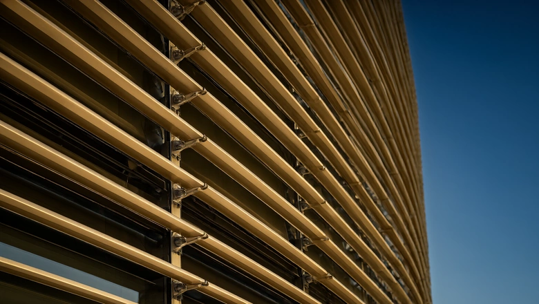
A kinetic facade is the one part of the envelope that can pass every laboratory test and still be wrong on the day the building opens. The mock-up proved a 4.0 m module built by the mock-up team in a clean bay. The tower has 1,600 blades on 40 drive lines, assembled by a different crew, in wind, at height, after eleven months of site storage. Commissioning exists to close that gap, and it fails most often not on the mechanics but on the evidence: nobody can show, six months later, that a given blade was ever commanded to 90°.
This article sets out what we commission, how each item is proven, and what the handover dossier has to contain. It follows the testing and verification matrix, the installation sequence and the actuation comparison, and it assumes the reader has already settled which of the two systems the elevation uses, because they commission in completely different ways.
What does kinetic facade commissioning actually prove?
Three proofs, and a fourth that is only paperwork. The first is mechanical: the blade still moves freely and returns where it should, after transport, lifting, storage and eighteen months of weather on an unfinished frame. The second is electrical: every command reaches the device that acts on it, and every feedback returns. The third is behavioural: with the input removed, the facade goes where the design says it goes. The fourth is documentary: the three above are recorded in a form a client can audit and a maintenance contractor can use in year seven.
| Proof | Object tested on site | Acceptance criterion | Record produced |
|---|---|---|---|
| Mechanical freedom | Every blade, sample torque on 10% | Full stroke with no binding; return to rest within tolerance | Torque sheet indexed to floor and grid |
| Activation threshold | Random blade sample per elevation face | Opens below 0.9 m/s, closes on calm | Anemometer log per face |
| Electrical continuity | Every drive line, sensor and feedback | Point-to-point confirmed at the BMS, not at the panel | Signed I/O matrix with timestamps |
| Fail-safe position | One zone per controller, then all zones | Reaches the declared position with power removed | Video plus position measurement |
| Sequence behaviour | Full elevation, live weather | Wind-stow, rain-close and night-rest in the designed order | Trend export from the BMS |
The order matters as much as the content. Electrical proof before behavioural proof, because a fail-safe test on an unproven signal tests the wrong thing; mechanical proof before everything, because a seized pivot will pass an electrical test perfectly and then strip its drive arm on the first command.
How is a passive kinetic screen commissioned?
Without a controller, so almost entirely by hand and by weather. There is no command path to verify and no I/O matrix to sign; the whole system is a torque balance between a spring and the air. That makes it cheap to commission and easy to get wrong, because the only instrument is a person watching a blade and a handheld anemometer.
| Parameter | How it is measured on site | What we accept |
|---|---|---|
| Pivot friction torque | Spring gauge on the blade tip, 10% sample per face, minimum three per module | Within ±15% of the mock-up value; no blade above the upper band |
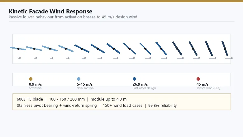
| Activation threshold | Handheld anemometer at blade height, blade watched for first movement | Full stroke starts below 0.9 m/s; the value is recorded, not assumed |
| Rest angle | Digital protractor against the blade chord, five blades per module | Within ±2° of the design rest angle, and consistent across the module |
| Blade clearance | Feeler gauge at the tightest point of the return sweep | Minimum 25 mm to the wall behind, 10 mm between adjacent blades |
| Free return | Blade held at 90° and released three times | Returns to rest without overshoot or sticking, all three times |
| Noise in service | Listen and record at 1 m during a full stroke | No squeal, scrape or metal contact; bearing dry and sealed |
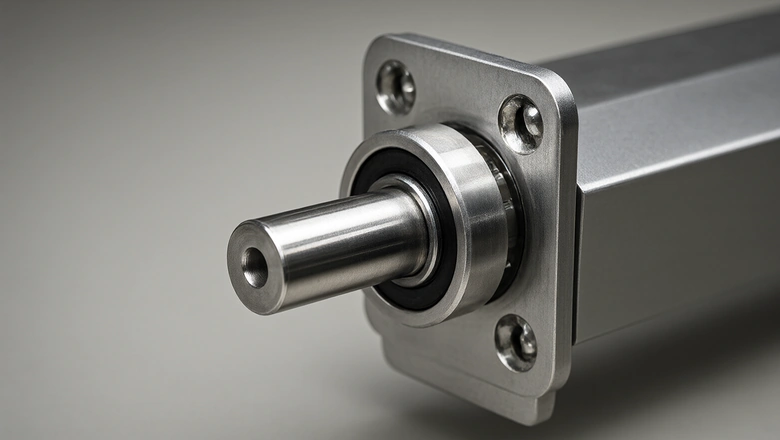
Two practical points. Commission the passive screen on a day with usable wind, and start at dawn, because the threshold you are looking for is below what a person can feel and the site anemometer reading at 15:00 on a Gulf elevation is not the number you are testing. And sample by elevation face rather than by floor: a corner face and a sheltered courtyard face behave differently, and averaging them hides the face that will generate the first complaint.
The threshold also drifts in service, which is why the handover dossier should carry the commissioned value per face rather than the design value. A blade that opened at 0.85 m/s at handover and opens at 1.0 m/s in year five has not failed — it is inside the 10% drift the cycle protocol allows — but the maintenance contractor needs the baseline to know that.
How is a motorised elevation commissioned?
In four layers, in order, and each layer signed before the next starts. Layer one is the field device alone, driven from a local service switch with the controller isolated. Layer two is the controller alone, with the field devices simulated. Layer three is the pair, on real signals. Layer four is the whole elevation under the building sequence. Skipping to layer four is the reason commissioning drags on for weeks: a fault found in a 40-zone sequence test could have been found in four minutes on a service switch.
| Layer | Scope | Typical duration, 40 drive lines | Pass condition |
|---|---|---|---|
| 1. Field device | Each actuator from its local switch, both limits | 2–3 days | Full 0–90° travel, limits set, no stall or overload trip |
| 2. Controller | Each zone with simulated inputs | 1–2 days | Correct output for every simulated condition |
| 3. Integrated pair | Real sensor to real actuator, zone by zone | 2–4 days | Command and feedback agree at the BMS point |
| 4. Building sequence | All zones, live weather and fire signal | 3–5 days, weather dependent | Sequence order, timing and priority as designed |
Layer one is where most latent defects surface. Typical findings on a 40-line elevation: two actuators with a limit set 4–6° short of 90°, one drive shaft coupling loose enough to slip under load, three blades binding on a module joint after thermal movement, and one actuator wired to the neighbouring zone at the riser. None of those is visible in a sequence test, because the sequence test sees a facade that appears to move.
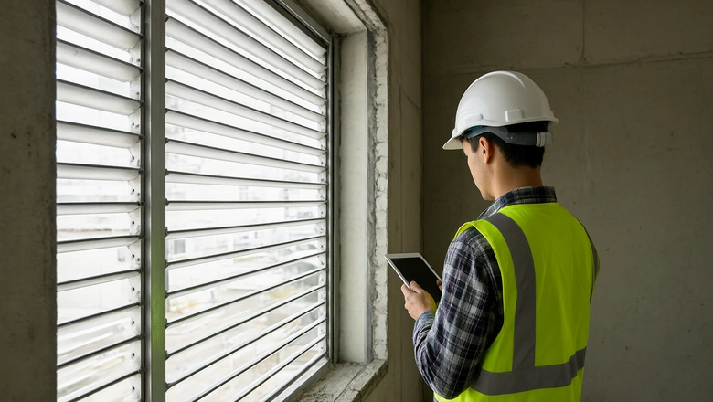
Which sensor checks decide the whole sequence?
The wind sensor decides almost everything, and it is the device most often installed badly. A single anemometer is a single point of failure for the whole elevation, so its siting matters more than its accuracy specification: clear of the facade's own turbulence, above the roof parapet, not in the lee of a plant enclosure, and with a mounting that does not vibrate. An anemometer reading 30% low because it sits in a separation bubble will let the screen stay open in a storm and destroy a blade row.
| Device | Commissioning check | Acceptance |
|---|---|---|
| Anemometer | Compare against a reference at the same height on a calm and a windy day | Within ±0.2 m/s over the working range; no sheltering above 15° of arc |
| Wind-stow threshold | Command injected at the controller, then confirmed at the actuator | Stow starts at 20–25 m/s and completes before the gust peak |
| Irradiance sensor | Shade and unshade, compare with a handheld reference | Tracks within 10%; no drift after a 60 °C surface soak |
| Rain contact | Wet the element, then dry it | Closes within 30 s of wetting; reopen delay set, not left at factory default |
| Fire alarm interface | Signal from the fire panel, zone by zone | Overrides every other command and holds the declared position |
| Manual override | Operate at the panel and at the local switch | Accessible to the fire service, documented, and tested with the BMS offline |
The priority order is the part clients ask about, and it should be written down before commissioning starts rather than negotiated during it. Our default: fire alarm overrides everything and drives the declared smoke position; wind-stow overrides normal operation and overrides the sun sequence; rain overrides the sun sequence but not wind-stow; the sun sequence has the lowest authority. If a project wants the facade to close on rain during a storm — which is the safe answer mechanically — then rain must sit above wind-stow, and that decision changes the actuator duty.
How is fail-safe behaviour proven?
By removing things and watching. Three removals, each on a representative zone first and then on the full elevation: remove power, remove the control signal, remove the wind input. Each has a different correct answer, and a system that fails well on one can fail badly on another.
| Failure imposed | Correct passive behaviour | Correct motorised behaviour | How it is proven |
|---|---|---|---|
| Mains power lost | Screen keeps shading; blades hold their balance | Drives to the declared fail position, then holds | Open the isolator; film the elevation; measure blade angle |
| Control signal lost | Not applicable; no signal path | Holds last position or stows, per the written fail mode | Disconnect the bus at the riser; watch for uncommanded travel |
| Wind input lost | Blades behave as if wind were absent | Treats the loss as a fault and stows on the timer | Disconnect the anemometer; confirm stow within the watchdog time |
| Actuator failure, one line | That blade row still moves passively | Zone reports the fault; other zones unaffected | Disconnect one actuator; confirm the fault reaches the BMS |
| Fire signal | Screen is not a smoke vent and is not relied upon | Overrides all, drives the declared position, reports | Inject at the panel; time the full travel; confirm at the head-end |
Two of these are routinely skipped and both matter. The lost-wind-input case is the one that decides whether the facade survives a sensor failure in a storm, and it is the only case where a well-built system must deliberately abandon its shading duty. And the single-actuator failure case is what separates a zone design that degrades from one that takes the elevation down with it: on a 15-blade drive line, one failed actuator must not stall its neighbours.
Key takeaways
- Commission the elevation, not the mock-up. The mock-up proved the design; the site proves the installation.
- Sequence the work mechanically, then electrically, then behaviourally. A fail-safe test on an unproven signal proves nothing.
- A passive screen has no I/O matrix; it is commissioned with a spring gauge, a protractor and a handheld anemometer, at dawn, sampled by elevation face.
- Point-to-point means the BMS point, not the panel terminal. The wrong-zone wiring defect only shows up when both ends are watched at once.
- Write the command priority order before commissioning begins, not during it. Fire over wind-stow over rain over sun is our default; reversing rain and wind-stow changes the actuator duty.
- Prove three failures: loss of power, loss of signal and loss of wind input. The third is the one that is always skipped and the one that saves the blade row.
- The handover dossier carries the commissioned value per face, not the design value, because the acceptance band in year five is measured against what was actually delivered.
What belongs in the handover dossier?
Nine sections, in a fixed order, in both paper and machine-readable form. The test that decides whether a dossier is good enough is simple: hand it to a maintenance contractor who has never seen the building, and ask them to plan next year's inspection from it alone. If they have to phone the facade contractor, the dossier is incomplete.
| Section | Content | Why it is needed in year five |
|---|---|---|
| 1. As-built elevation drawings | Zone boundaries, drive lines, sensor positions, access points | Any later modification needs the zone map to stay valid |
| 2. I/O matrix | Every point, address, range, alarm limit, signed | Controller replacement is impossible without it |
| 3. Commissioning records | Torque sheets, thresholds, stroke results, by floor and grid | The baseline every later reading is compared against |
| 4. Fail-safe test evidence | Video and measured position for each failure case | Proves the declared fail mode was real, not assumed |
| 5. Sequence and priority logic | Written priority table with thresholds and delays | The first thing an operator changes and the first thing lost |
| 6. Sensor calibration certificates | Field-checked values, reference instrument used | Distinguishes a drifting sensor from a real weather change |
| 7. O&M manuals | Actuator, controller, bearing, sealant, anodised finish | The maintenance contractor services five product families |
| 8. Spares and special tools | Actuator, bearing, spring, blade section, torque tool | Lead times, not prices, drive the downtime |
| 9. Punch list and closure | Open defects, agreed remedies, dates, sign-off | Defines what was accepted, and what was not |
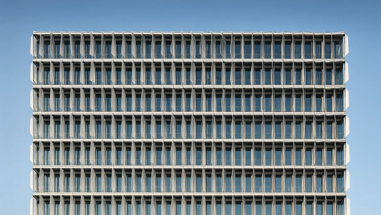
Two entries in that table are usually missing and both are cheap to produce. The priority table in section five is often held only in the programmer's head or in a controller file nobody can open; writing it as a one-page table at handover costs an hour and prevents a decade of argument. The commissioned values in section three are often replaced by design values because they are easier to copy, which quietly destroys the baseline the maintenance regime depends on.
How long does commissioning take?
On a 2,000 m² elevation with 1,600 blades on 40 drive lines, six to twelve weeks from first power to signed handover, and the variance is almost never the facade. It is the fire alarm interface, the BMS head-end availability and the weather. Plan for the sequence below and treat the last two weeks as a buffer rather than a schedule.
| Stage | Duration | Dependency that usually slips |
|---|---|---|
| Pre-commissioning survey | 3–5 days | Scaffolding or BMU access not released |
| Passive torque and threshold sweep | 1–2 weeks | Needs usable wind; a still week stalls it |
| Field device layer | 2–3 days | Permanent power to the riser |
| Controller and integration layers | 3–6 days | BMS head-end not yet live, so points cannot be signed |
| Building sequence and fail-safe | 1–2 weeks | Fire panel not yet programmable for the interface test |
| Seasonal verification | One full day, twice | Scheduled in the wrong season, so the shading duty is never seen |
| Dossier and punch closure | 2–4 weeks, in parallel | Records written at the end rather than during |
The seasonal item is the one clients resist and later regret. A facade commissioned in a mild month has never run its summer schedule, so nobody knows whether the sun sequence produces the glare it was bought to prevent. Two single days — one at peak cooling load, one at the coldest design day — cost almost nothing against the warranty argument they prevent.
Which commissioning clauses belong in the specification?
Eight, written to be copied into a tender without editing. Each closes a route by which a facade that looks complete is handed over unproven.
- Commission the installed elevation, not a sample. Functional testing shall be carried out on the installed facade; mock-up results shall not be accepted as evidence of site performance.
- Layered sign-off. Field device, controller, integrated pair and building sequence shall each be witnessed and signed before the next layer begins.
- Point-to-point at the head-end. Every command and feedback shall be proven at the BMS point, with both ends attended, and the signed matrix shall record the timestamp of each check.
- Thresholds measured, not assumed. Activation threshold, pivot torque and stroke limits shall be measured and recorded per elevation face, with the instrument and its calibration date.
- Written priority order. The command priority table, including thresholds and time delays, shall be issued as a controlled document at handover and mirrored in the controller program.
- Three fail-safe proofs. Loss of power, loss of control signal and loss of wind input shall each be demonstrated on a representative zone and on the full elevation, with video and measured blade position.
- Seasonal verification. A summer-peak and a winter-design verification visit shall be included in the commissioning scope, with the results added to the dossier.
- Baseline archived, not just issued. The commissioned values shall be stored in a form the maintenance contractor can read without the original installer, and referenced in the O&M manual.
Frequently asked questions
Does a passive kinetic facade need commissioning at all?
Yes, and it needs a different kind of commissioning. There is no controller, no I/O matrix and no sequence to test, but there is pivot friction torque, activation threshold and rest angle to measure blade by blade. A passive screen that is stiff at handover will not reach its 0.9 metre per second threshold, and the defect is invisible until the first hot week.
How long does kinetic facade commissioning take?
Six to twelve weeks on a 2,000 square metre elevation with about 1,600 blades on 40 drive lines, from first permanent power to signed handover. The facade itself is rarely the delay. The fire alarm interface, BMS head-end availability and the weather decide the programme, and a still week will stall a passive threshold sweep completely.
What is proven by a fail-safe test on a kinetic facade?
Three separate things, and they are not interchangeable. With power removed, the screen must reach or hold its declared position. With the control signal removed, it must not travel uncommanded. With the wind input removed, a motorised system must treat the loss as a fault and stow on its watchdog timer. The third case is the one usually skipped and the one that protects the blades.
Can commissioning results from the mock-up be used at handover?
No. The mock-up proves the design; the site proves the installation. Transport, lifting, storage, a different assembly crew and months of weather on an unfinished frame all change the result. A mock-up report is evidence of what the system can do, not of what was built, and tenders that accept it as handover evidence are buying an unproven facade.
What should the facade handover dossier contain?
Nine sections: as-built elevation drawings with zone boundaries, the signed I/O matrix, commissioning records by floor and grid, fail-safe test evidence, the written command priority table, sensor calibration certificates, O and M manuals, the spares and special tools list, and the closed punch list. The practical test is whether a maintenance contractor who has never seen the building can plan next year's inspection from it alone.
Handing over a kinetic screen?
Send us the elevation, the zone schedule and the control philosophy. We will return a commissioning matrix, the fail-safe test script and a dossier index you can issue with the tender.
Kinetic Facade Testing: Cycling, Water and Wind Verification
Kinetic Facade Actuation: Passive vs Motorised Louvers
Kinetic Facade Installation: Modules, Tolerances, Programme
Kinetic Facade Maintenance: Inspection & Lifecycle Cost
Kinetic Facade Wind Load: Activation to 45 m/s Design
Kinetic Facade Fire Safety: Fire Rating & Smoke Control
Kinetic Facade · Nov 10, 2026